Suction port assembly and a vacuum cleaner having the same

a vacuum cleaner and suction port technology, applied in the field of vacuum cleaners, can solve the problems of inability to determine if dirt is caught in and the suction port assembly is not efficient in cleaning large surface areas, and achieve the effect of efficient cleaning of the surfa

Inactive Publication Date: 2006-01-05
SAMSUNG GWANGJU ELECTRONICS CO LTD
View PDF9 Cites 32 Cited by
  • Summary
  • Abstract
  • Description
  • Claims
  • Application Information

AI Technical Summary

Benefits of technology

[0006] An aspect of the present invention is to solve at least the above problems and/or disadvantages and to provide at least the advantages described below. Accordingly, a

Problems solved by technology

Accordingly, the suction port assembly is not efficient in cleaning large surface areas.
In addition, since the top of the suction p

Method used


Image

  • Suction port assembly and a vacuum cleaner having the same
  • Suction port assembly and a vacuum cleaner having the same
  • Suction port assembly and a vacuum cleaner having the same

Examples


Embodiment Construction

[0024] Hereinbelow, certain embodiments of the present invention will be described in detail with reference to the accompanying drawings.

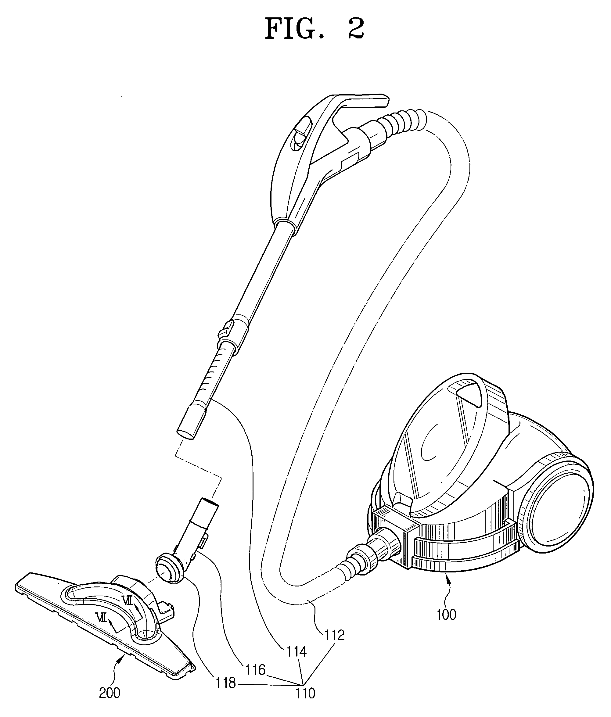
[0025]FIG. 2 is a perspective view of a vacuum cleaner according to one embodiment of the present invention. The vacuum cleaner comprises a cleaner body 100 mounting therein a vacuum source, a suction port assembly 200 for drawing in dirt from a surface being cleaned using a vacuum force generated by the vacuum source, and an extension path 110 connected to the suction port assembly 200 and to the cleaner body 100. Dirt is drawn in through the suction port assembly 200 to the cleaner body 100 through the extension path 110.

[0026] The extension path 110 comprises an extension tube connector 116, one end of which has a rotatable articulation joint or knuckle 118 that rotatably connects to the suction port assembly 200. A first end of an extension tube 114 is connected to the second or opposite end of the extension tube connector 116. One end of suc...


PUM


Abstract

A suction port assembly for a vacuum cleaner and a vacuum cleaner having such a suction port comprises upper and lower housings, a plurality of suction ports formed in the lower housing, and a plurality of suction paths formed in the upper and lower housings to guide the air drawn in through the suction ports. With this arrangement, the efficiency of cleaning the lateral sides of the suction port assembly can be enhanced, and thus a wide area can be efficiently cleaned.

Description

CROSS-REFERENCE TO RELATED APPLICATIONS [0001] This application claims the benefit of Korean Patent Application No. 2004-50990, filed Jul. 1, 2004, in the Korean Intellectual Property Office, the disclosure of which is incorporated herein by reference. FIELD OF THE INVENTION [0002] The present invention relates generally to a vacuum cleaner and more particularly, to a suction port assembly of a vacuum cleaner for drawing in dirt on a surface being cleaned. BACKGROUND OF THE INVENTION [0003] Vacuum cleaners draw in dirt on a surface being cleaned using a suction force generated by a vacuum source mounted in a main body thereof. As is known, vacuum cleaners comprise a cleaner body having therein a motor that generates a vacuum force, a suction port assembly facing a surface being cleaned to draw in dirt on the surface, and an extension path for guiding the dirt drawn in into the suction port to the cleaner body. The extension path often comprises an extension tube connector movably co...

Claims


Application Information

Patent Timeline
IPC IPC(8): A47L9/02
CPCA47L9/02A47L9/0072
Inventor LIM, JONG-KOOKCHOI, KEON-SOO
Owner SAMSUNG GWANGJU ELECTRONICS CO LTD
Why Eureka
Try Eureka