Casing feeder

a feeder and casing technology, applied in the direction of drilling casings, drilling pipes, borehole/well accessories, etc., can solve the problems of increasing the possibility of downtime, increasing the likelihood of thread damage, and time-consuming threaded connection and disconnecting process

Inactive Publication Date: 2006-01-05
WEATHERFORD TECH HLDG LLC
View PDF99 Cites 75 Cited by
  • Summary
  • Abstract
  • Description
  • Claims
  • Application Information

AI Technical Summary

Problems solved by technology

However, the process of threadedly connecting and disconnecting a casing is time consuming.
Furthermore, this process also increases the likelihood of damage to the threads, thereby increasing the potential for downtime.
One of the challenges of running casing using a top drive adapter is positioning the casing for engagement with the top drive adapter.

Method used


Image

  • Casing feeder
  • Casing feeder
  • Casing feeder

Examples


Embodiment Construction

[0051] In one embodiment, a top drive system for drilling includes a top drive adapter for gripping and rotating the casing. In another embodiment, a casing feeder is provided for positioning a casing for handling by the top drive adapter.

[0052] The casing feeder includes a pair of conveying members for engagement with the casing. The conveying member includes a conveying arm and a motor driven roller for engaging and lifting the casing. The conveying arms may be raised or lowered by a cylinder to engage the roller with the casing. Activation of the rollers moves the casing relative to the casing feeder. The casing feeder may also be equipped with a counting apparatus to determine the positioning of the casing in the torque head.

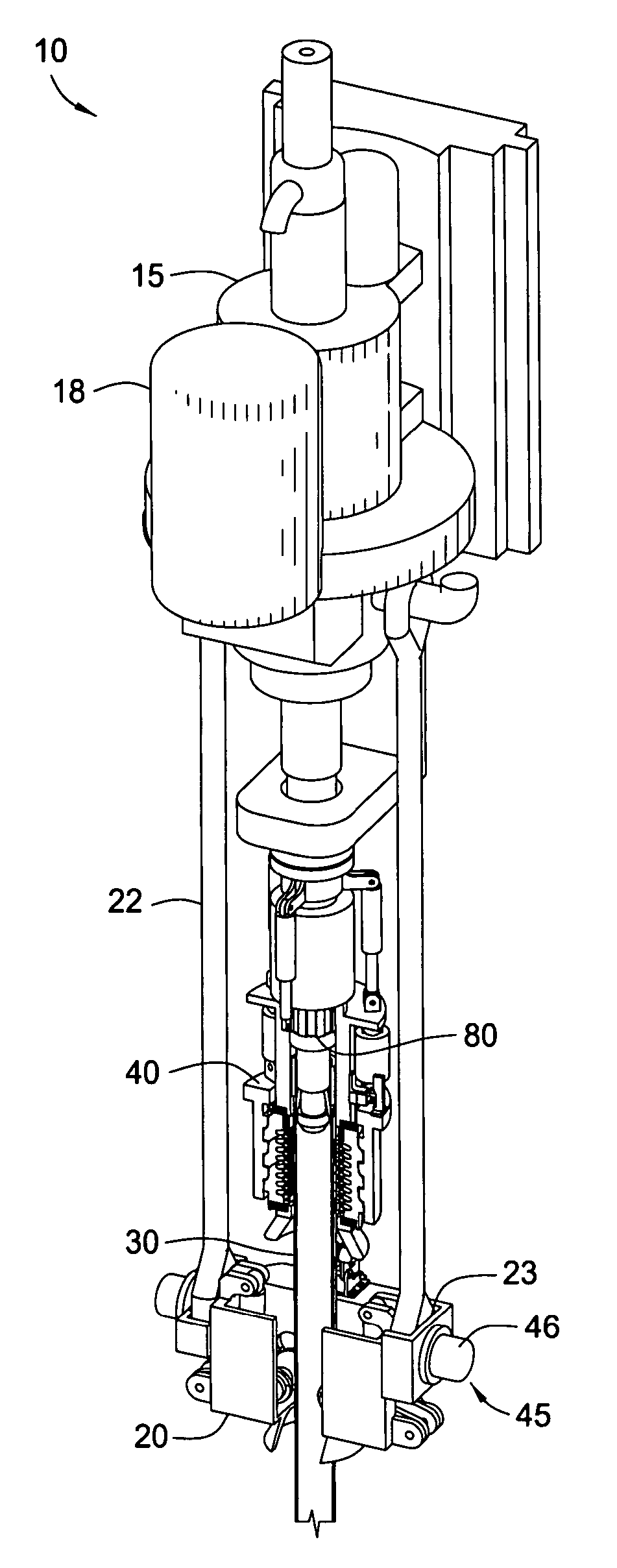
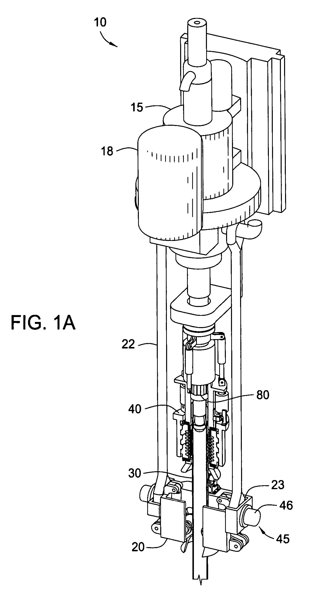
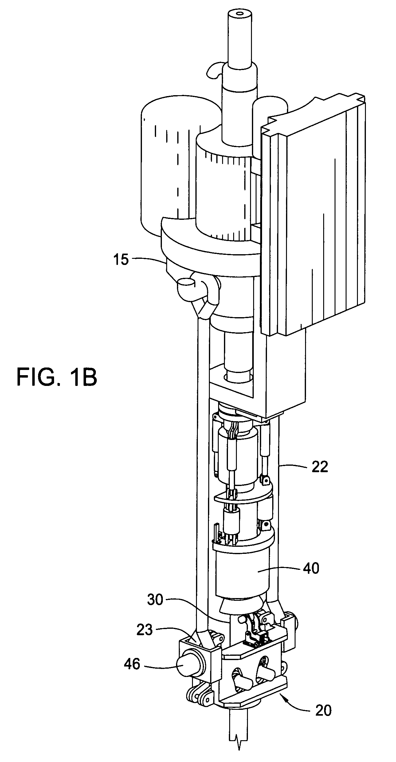
[0053]FIGS. 1A-1B show a top drive system 10 applicable to drilling with casing operations or a wellbore operation that involves picking up / laying down tubulars. The top drive system 10 may be suspended by a traveling block above the surface of a well. Gen...


PUM


Abstract

A top drive system for drilling with casing includes a casing feeder and a torque head. In one embodiment, the casing feeder is adapted to position a casing for engagement with the torque head. The casing feeder includes a pair of conveying arms for engagement with the casing. Each conveying arm may be raised or lowered by a cylinder. The conveying arms are equipped with a motor driven roller for engaging and lifting the casing. The casing feeder may also be equipped with a counting apparatus to determine the positioning of the casing in the torque head.

Description

CROSS-REFERENCE TO RELATED APPLICATIONS [0001] This application claims benefit of co-pending U.S. Provisional Patent Application Ser. No. 60 / 589,495, filed on Jul. 20, 2004, which application is herein incorporated by reference in its entirety. [0002] This application is also a continuation-in-part of co-pending U.S. patent application Ser. No. 10 / 738,950, filed on Dec. 17, 2003, which is a continuation of U.S. patent application Ser. No. 10 / 354,226 now U.S. Pat. No. 6,688,398, filed on Jan. 29, 2003, which is a continuation of U.S. patent application Ser. No. 09 / 762,698 now U.S. Pat. No. 6,527,047, filed on May 10, 2001, which is the National Stage of International Application No. PCT / GB99 / 02704, filed on Aug. 16, 1999, and published under PCT Article 21(2) in English, and claims priority of United Kingdom Application No. 9818366.8 filed Aug. 24, 1998. Each of the aforementioned related patents and patent applications is herein incorporated by reference in its entirety.BACKGROUND O...

Claims


Application Information

Patent Timeline
Patent Type & Authority Applications(United States)
IPC IPC(8): E21B19/18E21B19/06E21B19/16E21B19/24
CPCE21B19/06E21B19/24E21B19/16
Inventor PIETRAS, BERND-GEORG
Owner WEATHERFORD TECH HLDG LLC
Why Eureka
Try Eureka