Push switch

a push switch and push spring technology, applied in the field of push switches, can solve the problems of large size of the push switch, high production cost per component unit, etc., and achieve the effect of reducing the size of the entire push switch, facilitating the guide of the coil spring, and reducing the diameter of the push switch

Active Publication Date: 2006-01-05
ALPS ALPINE CO LTD
View PDF10 Cites 32 Cited by
  • Summary
  • Abstract
  • Description
  • Claims
  • Application Information

AI Technical Summary

Benefits of technology

[0044] The push switch according to an embodiment of the present invention can easily guide the coil spring. Furthermore, since the coil spring is stored in the through-hole in the operation body, the diameter of the push switch can be reduced.
[0045] The push switch according to an embodiment of the present invention includes a light-illuminating mechanism and a push lock mechanism while the size of the entire push switch can be reduced.
[0046] In the push switch according to an embodiment of the present invention, since the movable contacts are separated from the fixed contacts by contacting an area between a pair of protrusions, blades are not required. Moreover, the movable contacts can come into contacted with and can be separated from the fixed contact by push operating the operation shaft, and the size of the push switch can be reduced.
[0047] In the push switch according to an embodiment of the present invention, when the entire movable contact unit is pushed by the resilient member, the movable contact unit cannot tilt as easily. Thus, there is a possibility in that an error in manufacturing may cause a difference in the height of the fixed contacts, causing the movable contacts not to be able to fully contact the fixed contacts. However, as in the...

Problems solved by technology

Since a long light-guiding portion 26 has to be formed as a single piece with the push button 21, t...

Method used


Image

  • Push switch
  • Push switch
  • Push switch

Examples


embodiments

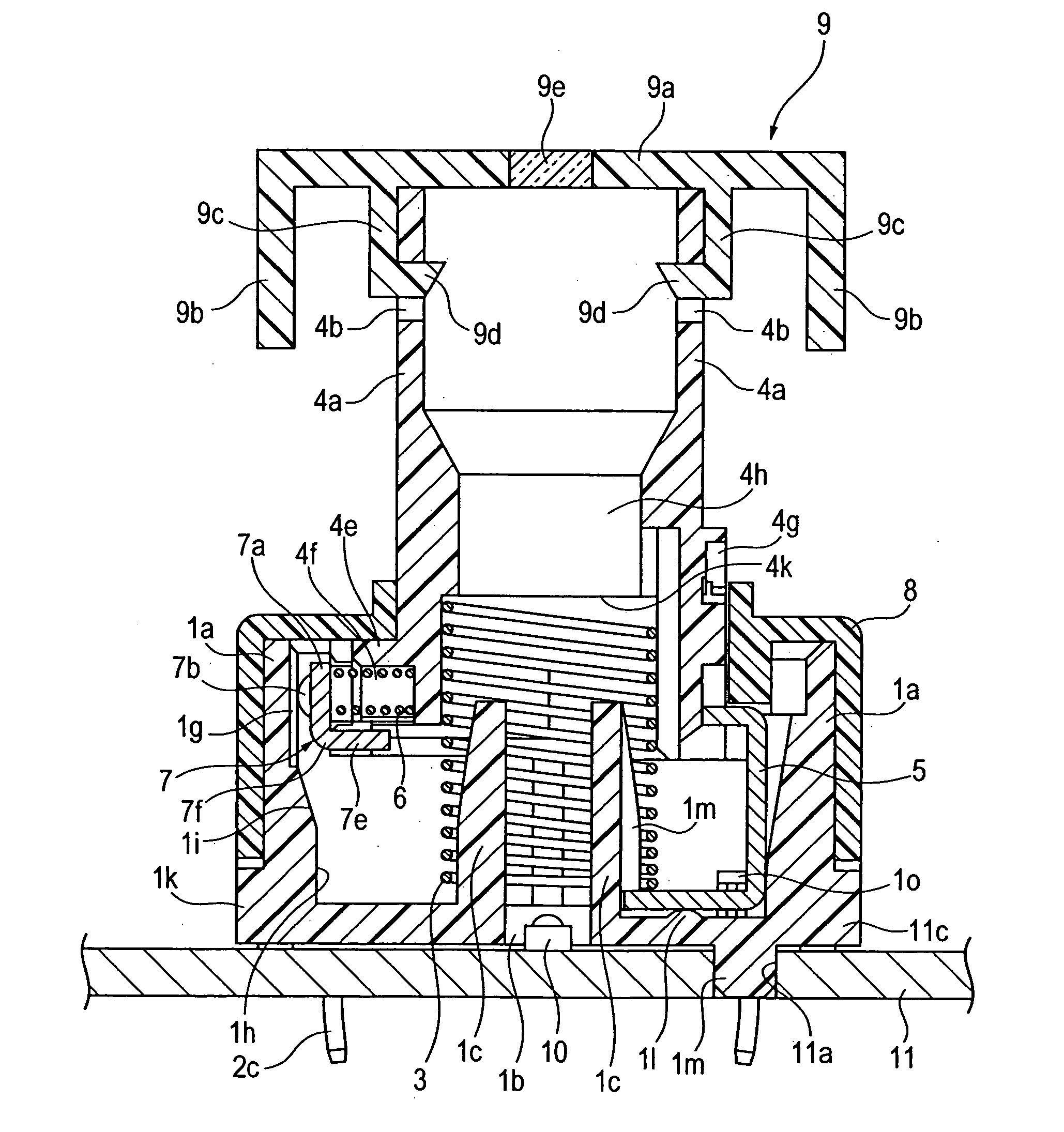
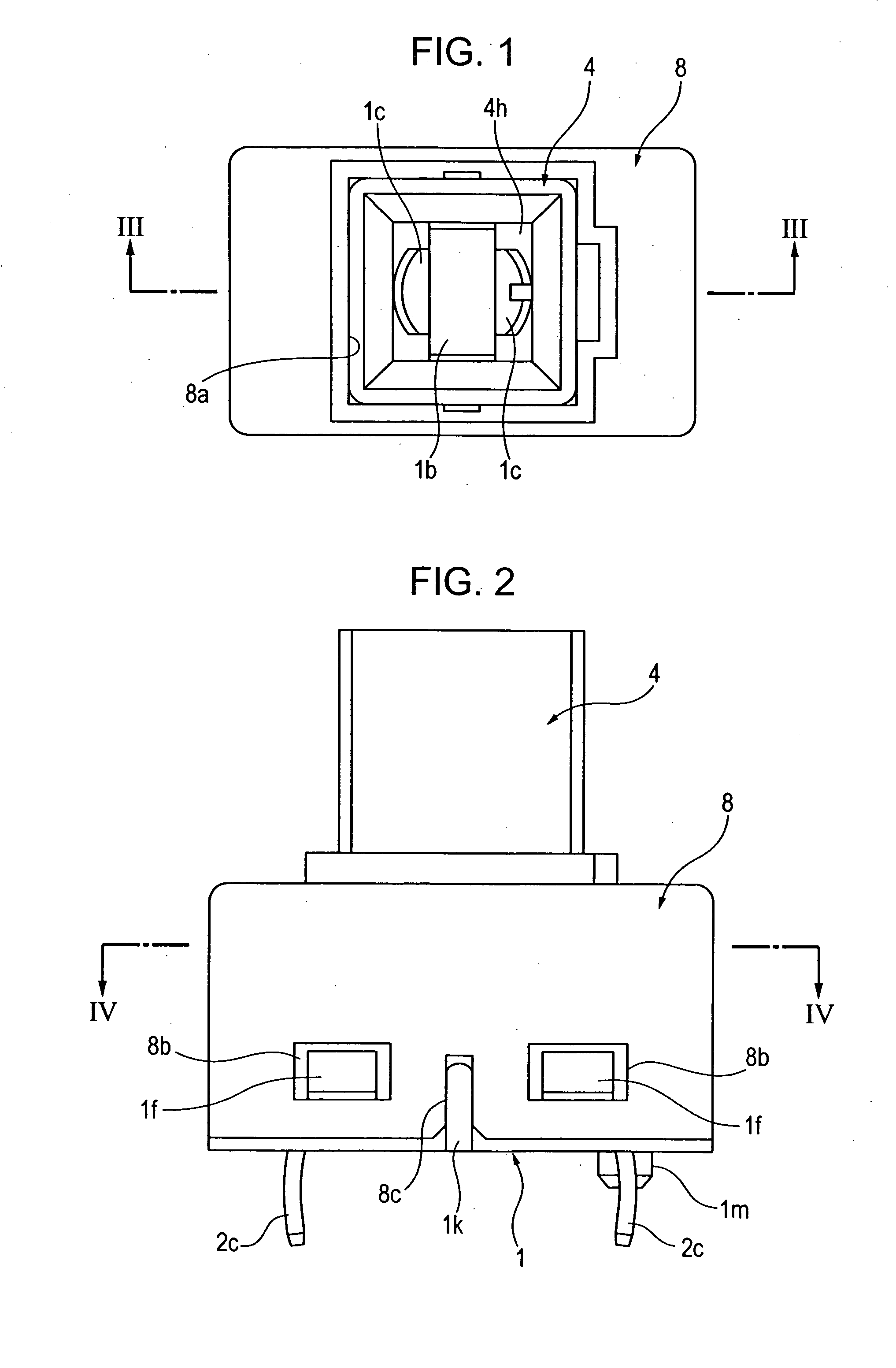
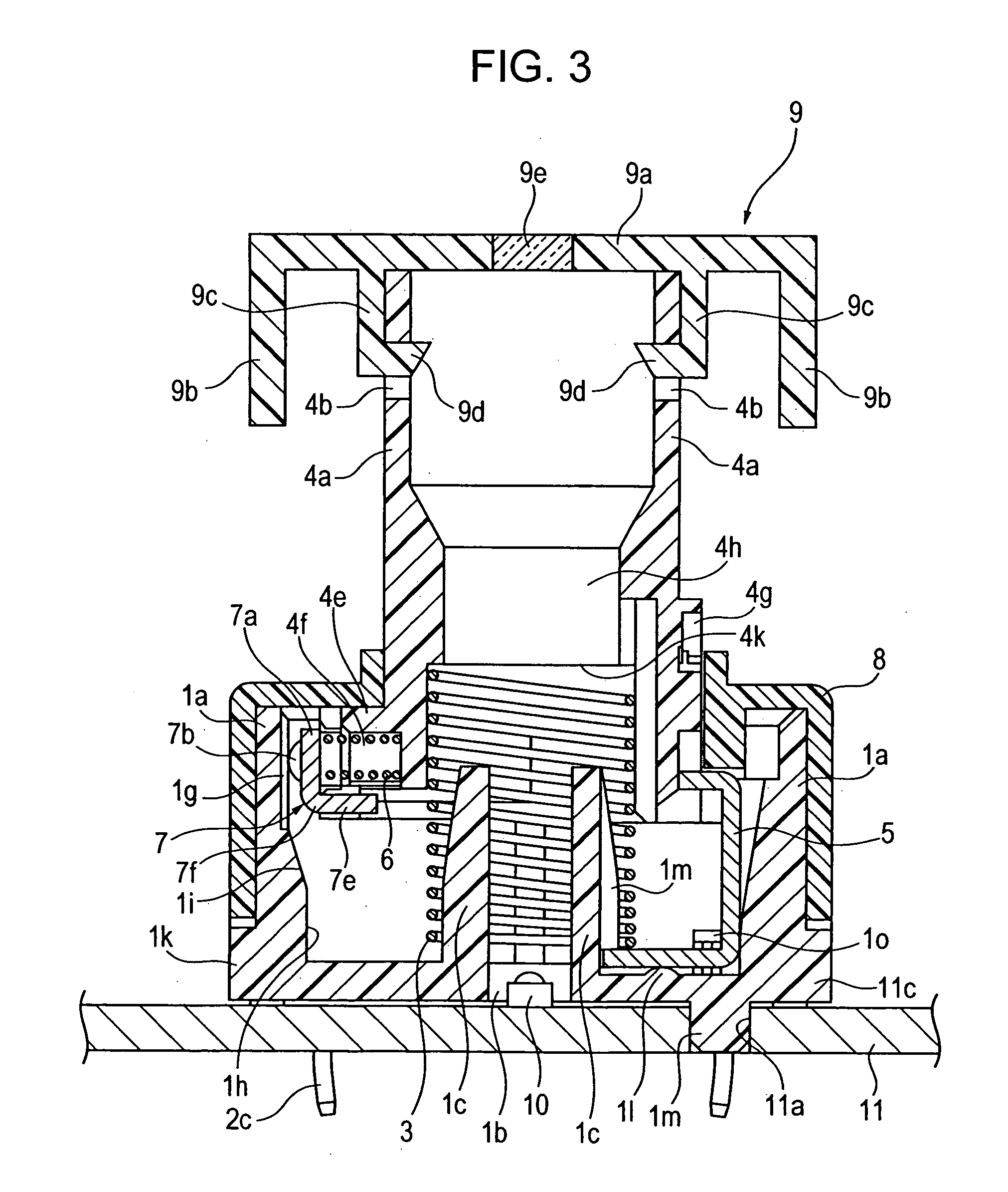
[0064] The drawings referred to for describing the push switch according to an embodiment are as follows: FIG. 1 is a plan view of the push switch according to an embodiment; FIG. 2 is a front view of the push switch illustrated in FIG. 1; FIG. 3 is a cross-sectional view taken along line III-III in FIG. 1; FIG. 4 is a cross-sectional view taken along line IV-IV in FIG. 2; FIG. 5 is a schematic view of the vicinity of fixed contacts of a case of the push switch according to an embodiment; FIG. 6 is a perspective view of the push switch according to an embodiment; FIG. 7 is a perspective view from the back side of the FIG. 6; and FIG. 8 is cross-sectional view of the push switch according to an embodiment wherein a knob is pressed down.

[0065] As illustrated in FIGS. 1 to 8, the push switch according to an embodiment includes a case 1. The case 1 is made of synthetic resin and is produced by a molding process. The case 1 includes sidewalls 1a forming the four sides of the case 1, a r...


PUM


Abstract

A push switch includes an operating body, a case, a return spring, and a light source. The operating body is controlled by push operation, includes a through-hole in the center and a display portion at the upper edge of the through-hole, and supports a movable contact unit. The case has the insert hole on a bottom surface opposing the through-hole and fixed contact units on an inner surface of the sidewall. The movable contact unit comes into contact with fixed contact units. The return spring is interposed between the case and the operating body and returns the position of the operating body in the reverse direction of the push operation. The light source stored in the insert hole and the through-hole. The through-hole is formed linearly in the direction the operating body is moved during the push operation so that the light source does not interfere with the operating body.

Description

BACKGROUND OF THE INVENTION [0001] 1. Field of the Invention [0002] The present invention relates to a push switch including a light-illuminating structure for a lockout of a power window. More specifically, the present invention relates to a push switch having a fixed contact unit on the inner surface of a case and a movable contact unit that comes into contact with and separates from the fixed contact unit on an operation shaft. [0003] 2. Description of the Related Art [0004] The structure of a first known push switch including a light-illuminating structure described in Japanese Unexamined Patent Application Publication No. 63-168932 is illustrated in FIG. 9. [0005] As illustrated in the drawing, the push switch includes a push button 21 having a transparent display portion on the front surface, a non-transparent escutcheon 23 having a button hole 22 for passing through the push button 21, a non-transparent printed circuit board 25 being disposed on the back side of the escutcheo...

Claims


Application Information

Patent Timeline
IPC IPC(8): H01H13/14
CPCH01H13/28H01H13/023
Inventor SASAKI, ATSUMIMORI, TOSHIHARUSAWADA, KENJI
Owner ALPS ALPINE CO LTD
Why Eureka
Try Eureka