Amplifier circuit for converting the current signal from an optical receiving element into a voltage signal

an amplifier circuit and current signal technology, applied in the direction of amplifiers, light-controlled amplifiers, electrical apparatus, etc., can solve the problems of undesired oscillation, reduced stability and phase margin, and general inapplicability of first alternative, so as to improve the phase margin of the transimpedance amplifier

Active Publication Date: 2006-01-05
AVAGO TECH INT SALES PTE LTD
View PDF6 Cites 31 Cited by
  • Summary
  • Abstract
  • Description
  • Claims
  • Application Information

AI Technical Summary

Benefits of technology

[0009] The present invention is based on the idea of connecting, in parallel with an adjustable resistor which is already present and which is preferably formed as an MOS transistor, a series circuit comprising a capacitor and a further adjustable resistor, which is likewise formed as an MOS transistor. The se...

Problems solved by technology

A lower gain is associated with a reduced stability and phase margin of the transimpedance amplifier and can lead to undesired oscillations.
The fir...

Method used


Image

  • Amplifier circuit for converting the current signal from an optical receiving element into a voltage signal
  • Amplifier circuit for converting the current signal from an optical receiving element into a voltage signal

Examples


Embodiment Construction

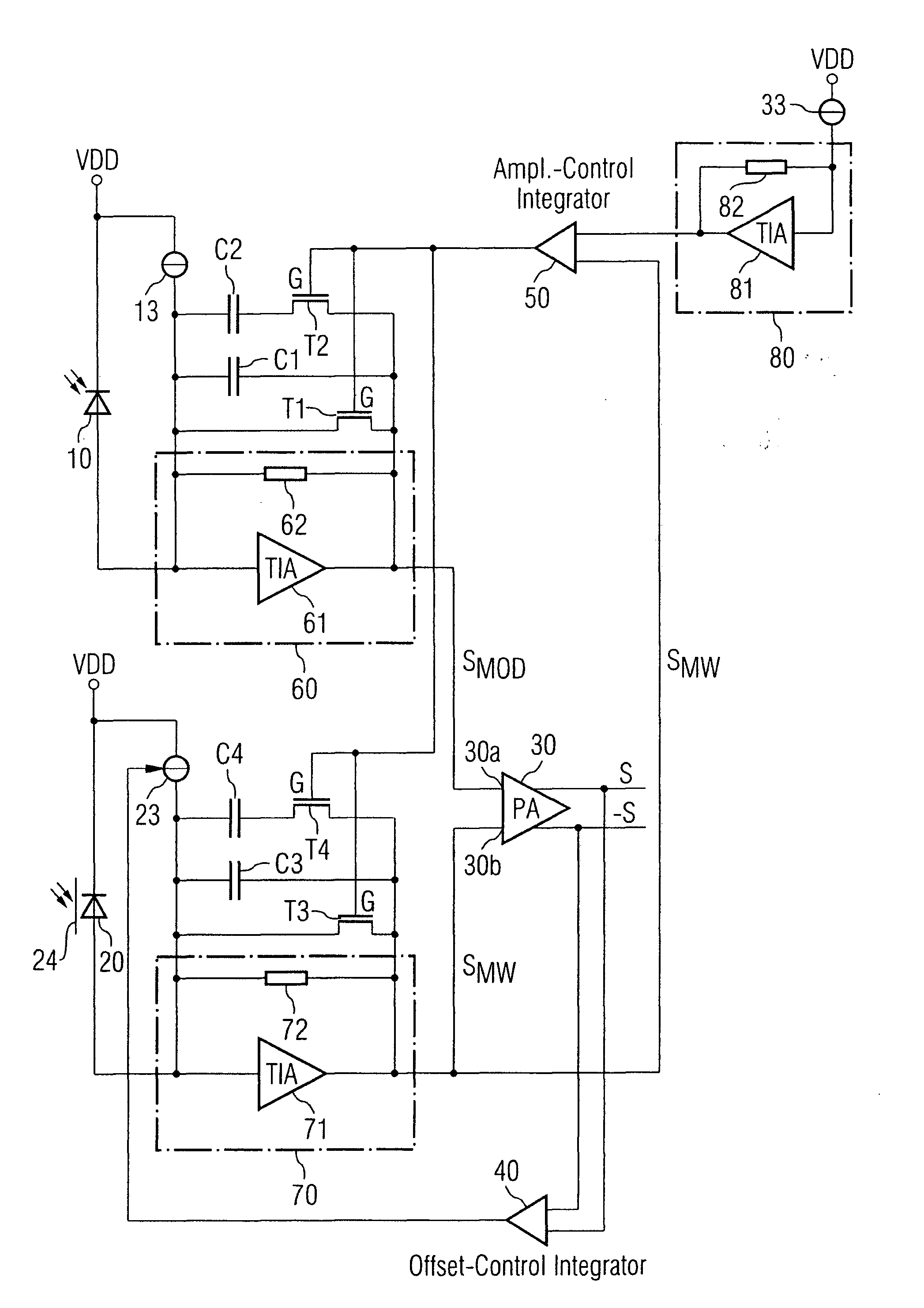
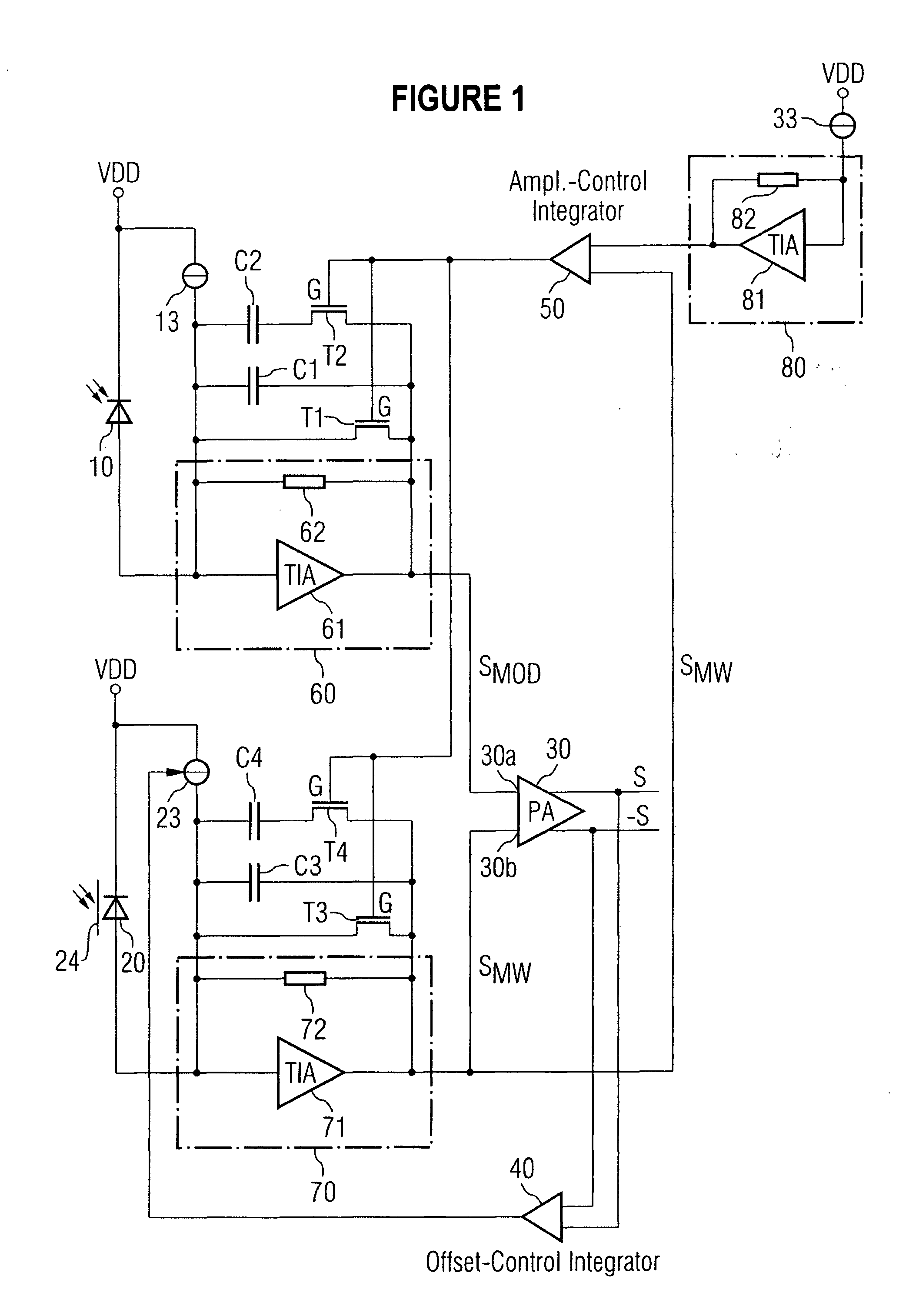
[0017]FIG. 1 describes a circuit arrangement in which a first optical receiving element 10 in the form of a photodiode is provided, which converts an optical information signal into an electrical signal. The electrical signal is amplified in a preamplifier 60 and is supplied to the one input 30a of a post-amplifier 30, which is a differential amplifier. The preamplifier is a transimpedance amplifier 60, which comprises a voltage amplifier 61 and a feedback resistor 62. The substantially square-wave output signal from the photodiode 10 at the input of the transimpedance amplifier 60 has superimposed on it a constant current from a fixed current source 13, which provides a suitable offset at the input of the voltage amplifier 61.

[0018] A plurality of circuit elements are connected in parallel with the feedback resistor 62. A first circuit element connected in parallel with the feedback resistor 62 is a field effect transistor T1. A control signal provided by a comparison device 50, e...


PUM


Abstract

An amplifier circuit for converting the current signal from an optical receiving element into a voltage signal. The amplifier circuit includes a transimpedance amplifier having a differential amplifier and a feedback resistor, a first adjustable resistor which is connected in parallel with the feedback resistor and whose resistance value is defined by a first control signal, and a series circuit connected in parallel with the feedback resistor. The series circuit includes a first capacitor and a second adjustable resistor, whose resistance value is defined by a second control signal. The two adjustable resistors are preferably formed as MOS resistors and have the same control signal applied to them. The amplifier circuit permits the provision of a high dynamic range during the operation of a transimpedance amplifier.

Description

RELATED APPLICATION [0001] The present application claims priority of U.S. Patent Application Ser. No. 60 / 585,308 filed by Torsten Harms and Stefan van Waasen on Jul. 2, 2004.FIELD OF THE INVENTION [0002] The invention relates to an amplifier circuit for converting the current signal from an optical receiving element into a voltage signal, using a transimpedance amplifier. In particular, the invention relates to an amplifier circuit having a transimpedance amplifier, which provides a high dynamic range in converting a photocurrent into voltage values. BACKGROUND OF THE INVENTION [0003] For the purpose of receiving and regenerating optical signals after passage through a transmission path, digital optical receivers are known which comprise a receiver circuit, in which the optical signal is converted into an analog electrical signal, and a digital signal processing part, in which the analog signal is regenerated into a digital data signal with standardized amplitude and clock informat...

Claims


Application Information

Patent Timeline
IPC IPC(8): H03F3/08
CPCH03F3/082H03F3/45973H03F3/087
Inventor HARMS, TORSTENWAASEN, STEFAN VAN
Owner AVAGO TECH INT SALES PTE LTD
Why Eureka
Try Eureka