
Laser television

a laser television and television technology, applied in the field of laser televisions, can solve the problems of increased manufacturing cost, large loss of intensity, and uneven intensity distribution, and achieve the effect of preventing the speckle noise of laser televisions

Inactive Publication Date: 2006-01-05
SAMSUNG ELECTRONICS CO LTD
View PDF5 Cites 12 Cited by
  • Summary
  • Abstract
  • Description
  • Claims
  • Application Information

AI Technical Summary

Benefits of technology

[0011] Accordingly, the present invention has been made to solve the above-described problems occurring in the prior art, and an object of the present invention is to provide a diffraction grating for preventing the speckle noise of a laser television for generating images on a screen using different wavelengths of light.

Problems solved by technology

The lasers generate different wavelengths of light, the high degree of interference of which causes irregular intensity distribution when images are displayed on screens.
However, when light passes through the ground glass, a large loss of intensity occurs.
However, a means for removing speckle noise including a diffraction grating has a problem in that it must include a plurality of diffraction gratings, which have different grating cycles corresponding to different wavelengths of interferential light.
This increases the manufacturing cost and makes it difficult to align optical axes.

Method used


Image

  • Laser television
  • Laser television
  • Laser television

Examples


Embodiment Construction

[0018] Hereinafter, preferred embodiments of the present invention will be described with reference to the accompanying drawings. In the following description of the present invention, a detailed description of known functions and configurations incorporated herein will be omitted when it may make the subject matter of the present invention rather unclear.

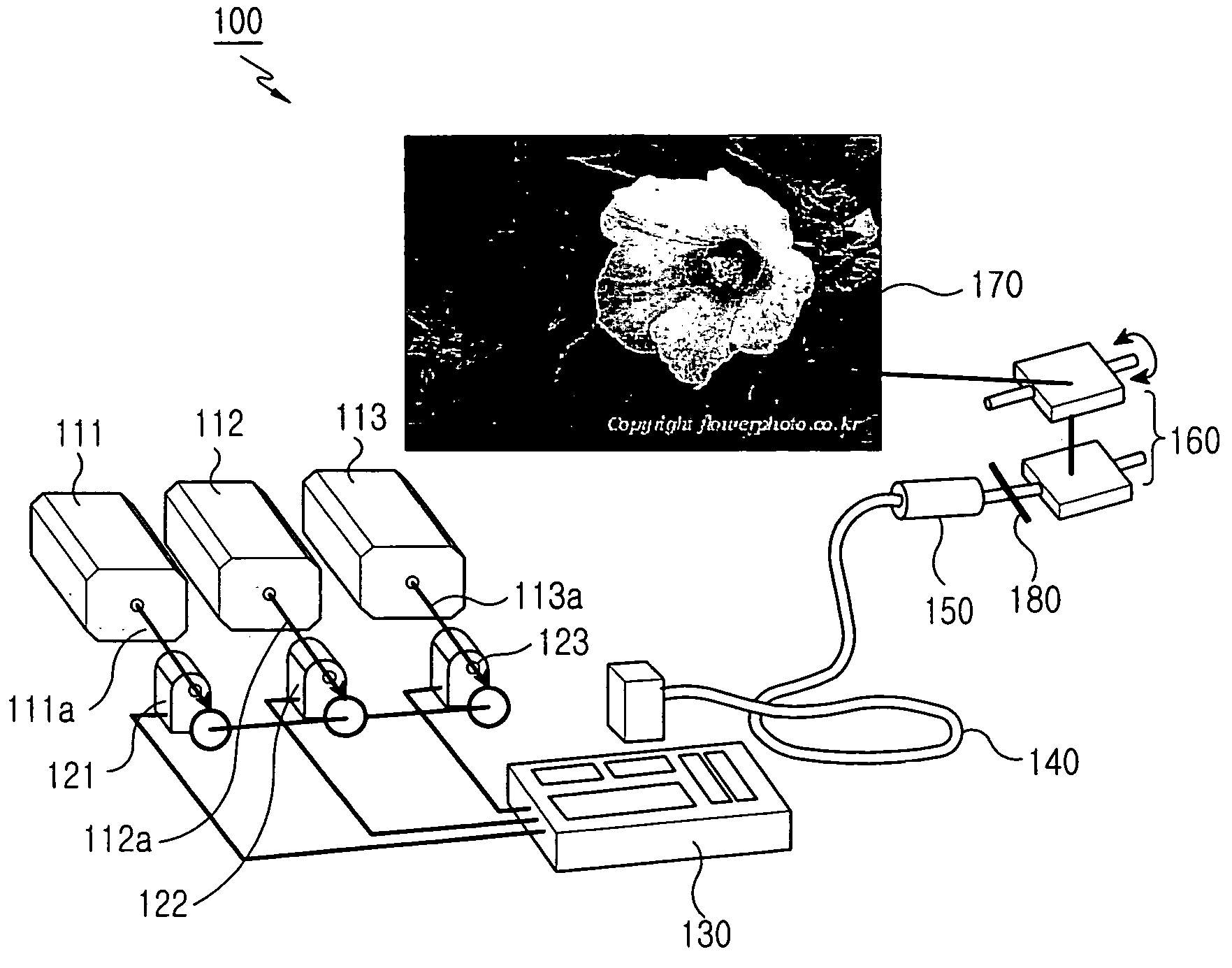
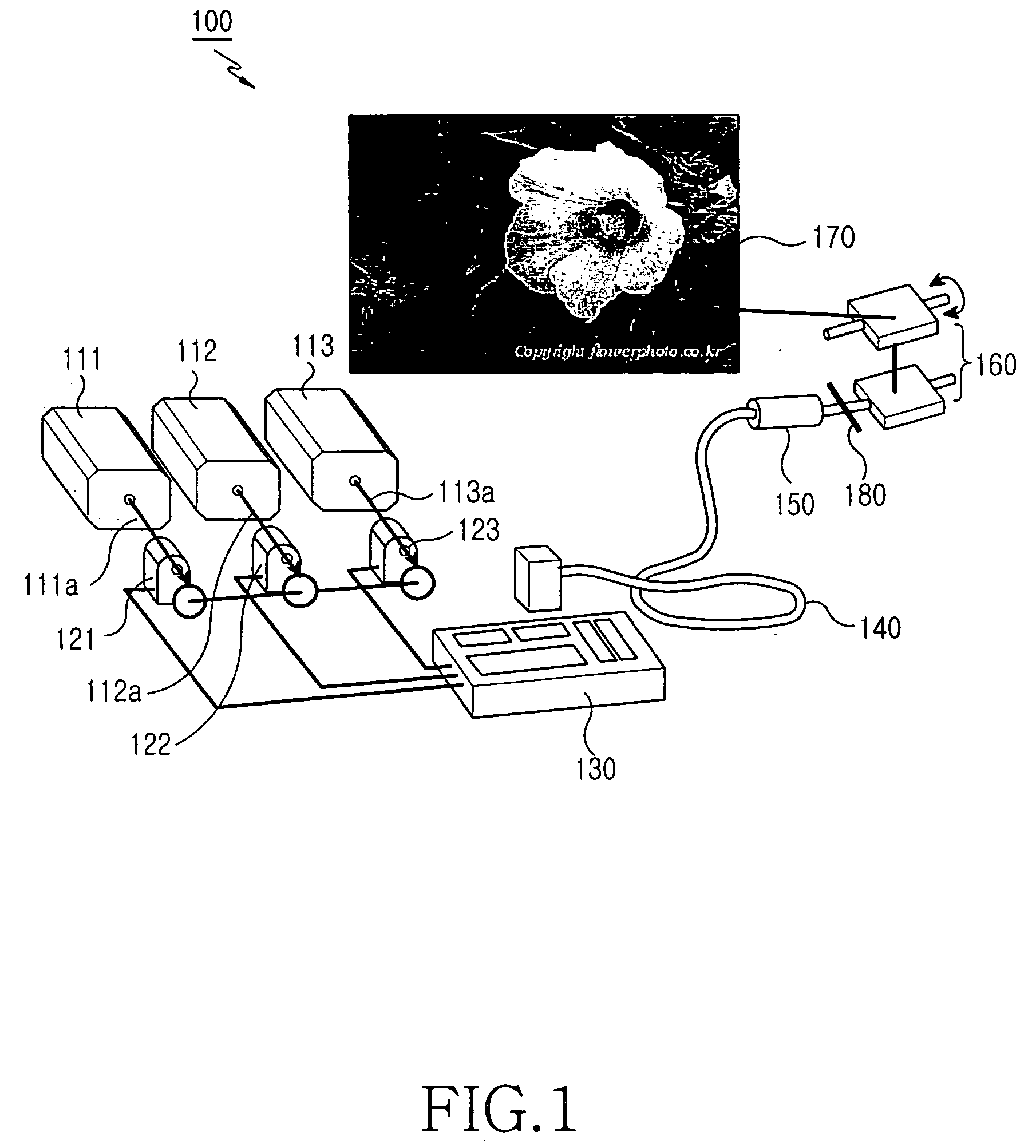
[0019]FIG. 1 shows the construction of a laser television according to an embodiment of the present invention. Referring to FIG. 1, a laser television 100 includes a plurality of lasers 111, 112, and 113 for generating different wavelengths of interferential light; a scanner 160 for displaying color images on a screen, the images being composed from the interferential light; a phase diffuser 180 positioned between the lasers 111, 112, and 113 and the scanner 160; a plurality of modulators 121, 122, and 123 for modulating the different wavelengths of light outputted from the lasers, respectively; a controller 130 for controlling th...


PUM


Abstract

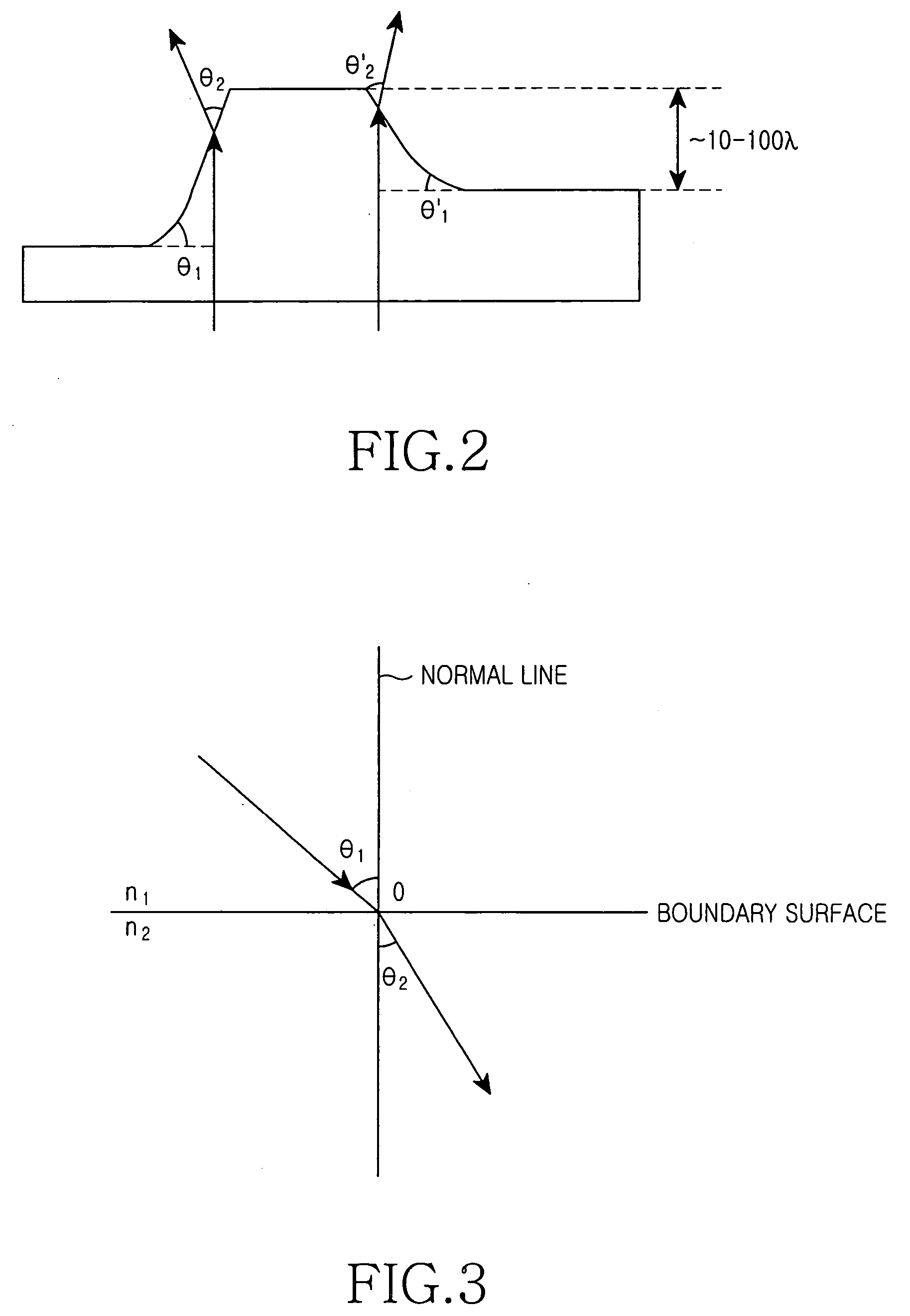
A laser television including a plurality of lasers for generating different wavelengths of interferential light; a scanner for displaying color images on a screen composed from the light; and a phase diffuser positioned between the lasers and the scanner for diffusing the light from the lasers according to the light's wavelength. The phase diffuser having a boundary surface, through which the light is outputted to the scanner. The boundary surface is slanted with a predetermined angle to regulate the range of diffraction of the light according to the wavelength.

Description

PRIORITY [0001] This application claims priority to an application entitled “Laser Television” filed with the Korean Intellectual Property Office on May 18, 2004 and assigned Serial No. 2004-35035, the contents of which are hereby incorporated by reference. BACKGROUND OF THE INVENTION [0002] 1. Field of the Invention [0003] The present invention relates to a laser television, and more particularly to a laser television having a means for controlling a speckle phenomenon caused by different wavelengths of light. [0004] 2. Description of the Related Art [0005] In general, image regeneration apparatuses including projection and laser televisions have a plurality of lasers for generating interferential light of basic colors, e.g., red, green, and blue, so that color images can be displayed on a screen. In other words, the image regeneration apparatuses can display color images using a combination of different wavelengths of light. [0006] The lasers generate different wavelengths of ligh...

Claims


Application Information

Patent Timeline
IPC IPC(8): H04N5/64H04N5/70H04N5/74
CPCH04N9/3129H04N5/74
Inventor AHN, PIL-SOOPAVEL, SERAFIMOVICHLEE, JIN-HOMUN, YONG-KWEUNCHEONG, BYOUNG-HO
Owner SAMSUNG ELECTRONICS CO LTD
Learn More