Vibration-damping hammer

a vibration-damping hammer and hammer technology, applied in the field of hammers, can solve problems such as discomfort or even injury to the wrist of users, and achieve the effect of minimizing efficiency and minimizing shock

Inactive Publication Date: 2006-01-12
HUNG YI KUNG
View PDF6 Cites 12 Cited by
  • Summary
  • Abstract
  • Description
  • Claims
  • Application Information

AI Technical Summary

Benefits of technology

[0006] The main objective of the present invention is to provide a vibration-damping ham

Problems solved by technology

However, because the head is directly connected with the handle without a vibration damping design, when striking the head against an object, such as a nail or chisel,

Method used


Image

  • Vibration-damping hammer
  • Vibration-damping hammer
  • Vibration-damping hammer

Examples


Embodiment Construction

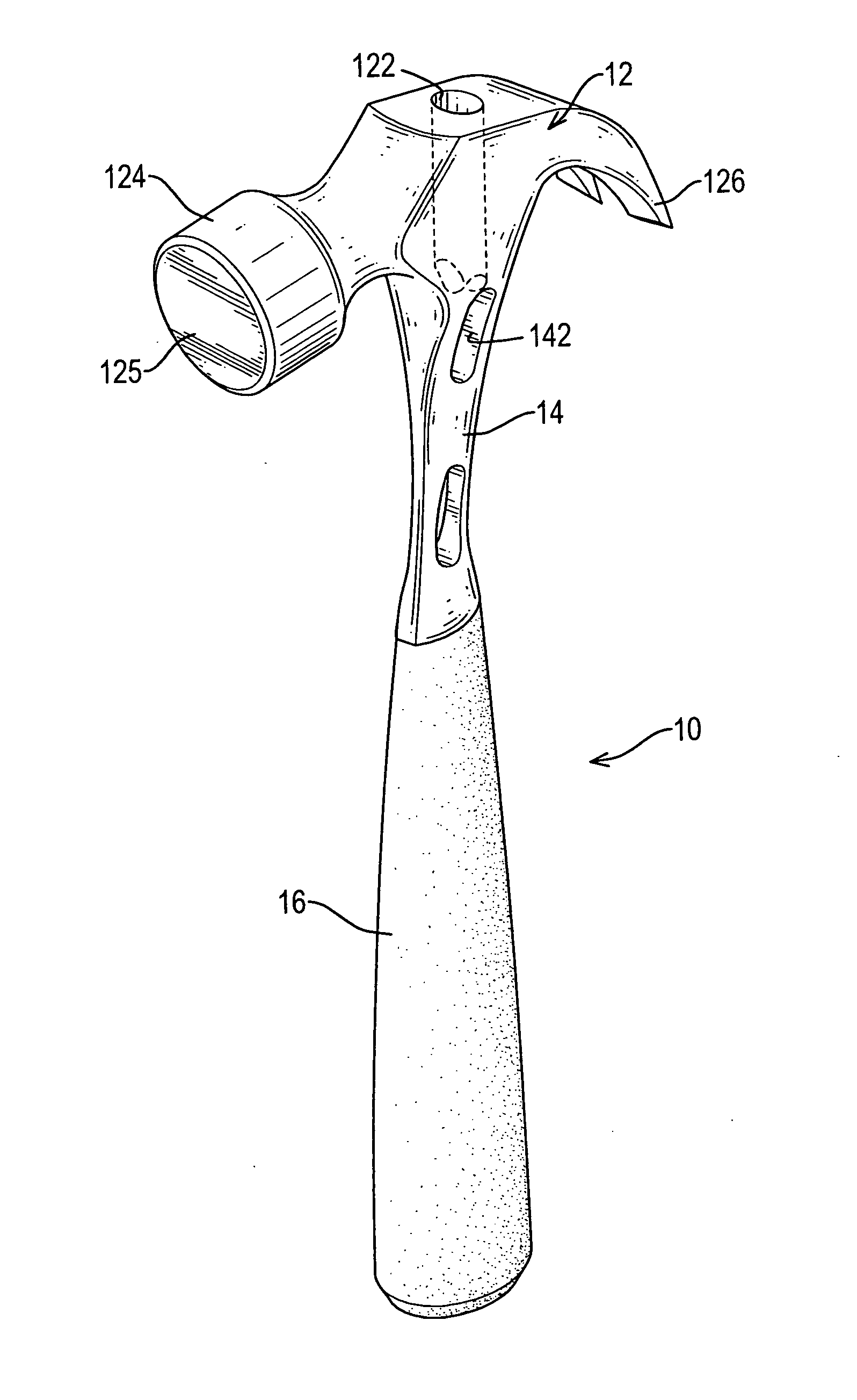
[0011] A vibration-damping hammer in accordance with the present invention comprises a head with a neck portion, a handle and at least one damping hole defined in the head, particularly in the neck. The at least one damping hole makes the neck more flexible and mitigates vibration transmission, whereby most vibrating energy is eliminated. Therefore, the hammer has less vibration whereby the comfort enables the user to avoid working injury.

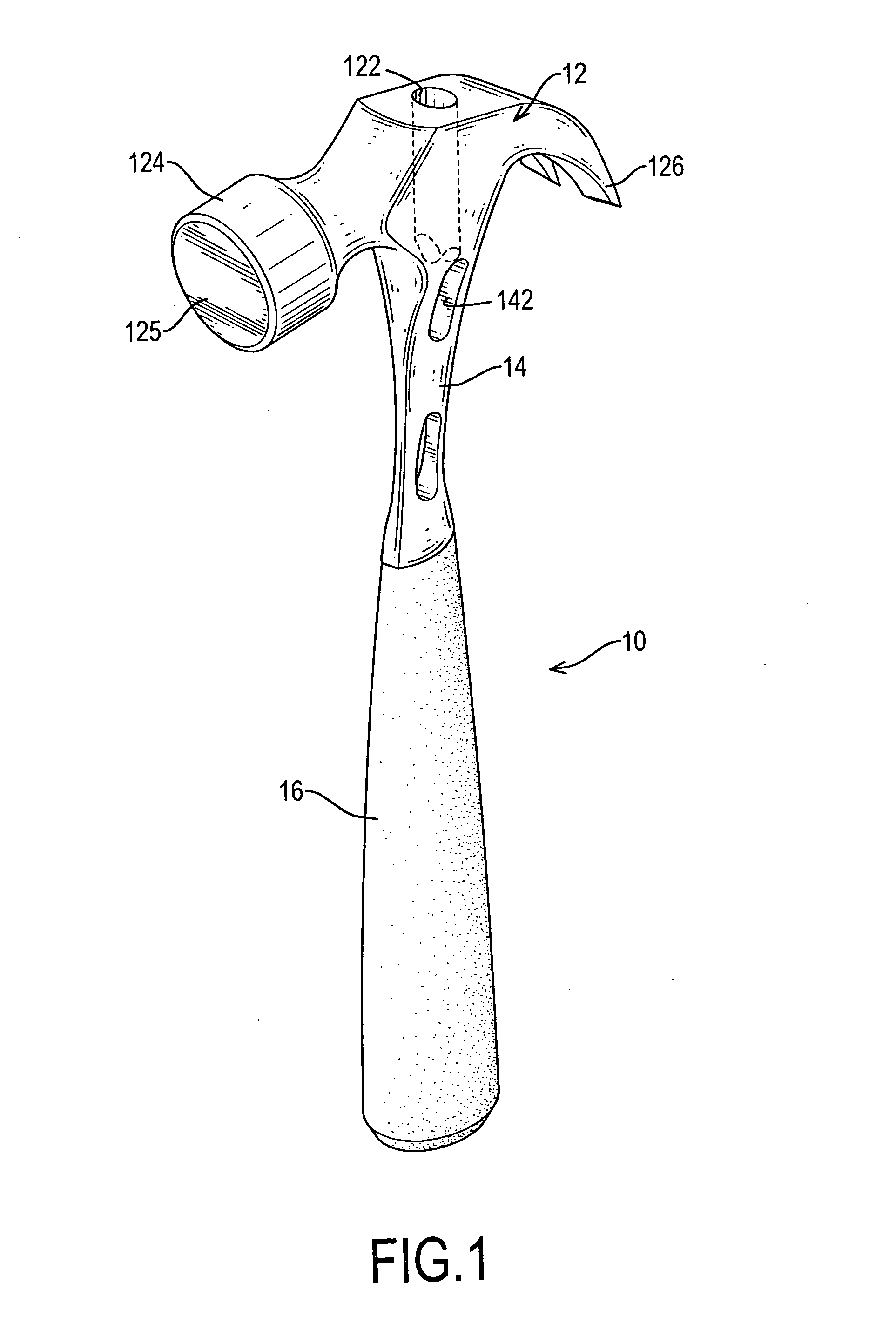
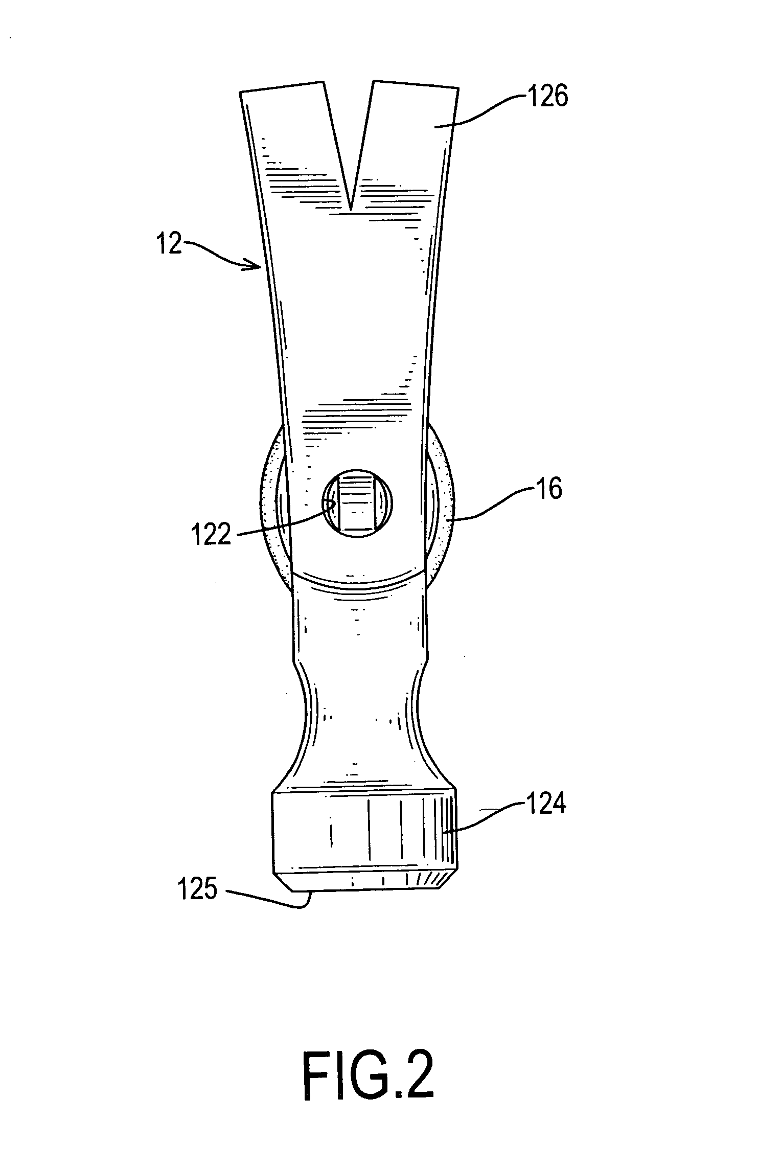
[0012] With reference to FIGS. 1 and 2, a preferred embodiment of the vibration-damping hammer (10) comprises a head (12), a neck (14), a handle (16), at least one damping hole (142) and an optional rod hole (122) defined in the head (12).

[0013] The head (12) has a top face, a cylindrical front end (124) with a striking surface (125), and a tapered forked end (126) for removing nails (not shown). The striking surface (125) is adapted to strike an object when the hammer is swung. The tapered forked end (126) serves as a claw to grip and pull the n...


PUM


Abstract

A vibration-damping hammer has a head with a neck portion, a handle attached to the neck portion and at least one damping hole defined in the head, particularly in the neck. The at least one damping hole makes the neck sufficiently flexible and mitigates vibration transmission and so eliminates most vibrating energy. Therefore, the hammer has less vibration whereby the comfort enables the user to avoid working injury.

Description

BACKGROUND OF THE INVENTION [0001] 1. Field of the Invention [0002] The present invention relates to a hammer, and more particularly to a hammer that has vibration-damping efficiency. [0003] 2. Description of Related Art [0004] Conventional hammers typically include a steel or iron head immovably mounted on a handle that is usually covered with a flexible and anti-slip sleeve to provide a gripping surface. However, because the head is directly connected with the handle without a vibration damping design, when striking the head against an object, such as a nail or chisel, vibrations will be transmitted through the handle to the hand of the user. Over a period of usage, the vibrations can cause discomfort or even injury to a user's wrist. [0005] The present invention has arisen to mitigate or obviate the disadvantages of the conventional hammer. SUMMARY OF THE INVENTION [0006] The main objective of the present invention is to provide a vibration-damping hammer that has multiple holes ...

Claims


Application Information

Patent Timeline
IPC IPC(8): B25D1/12
CPCB25D1/12
Inventor HUNG, YI-KUNG
Owner HUNG YI KUNG
Why Eureka
Try Eureka