Heated eyelash curler

Inactive Publication Date: 2006-01-12
CHO YONG HOON
View PDF4 Cites 21 Cited by
  • Summary
  • Abstract
  • Description
  • Claims
  • Application Information

AI Technical Summary

Benefits of technology

[0018] This invention relates to a heated eyelash curler, comprising a curling head portion having an arcuate top surface on one end and a protection case on the other end. The protection case serves as a handle for the device. The curling head portion includes a heating element laid on the arcuate top surface caged inside a plurality of bridges or protected between protruding comblike spikes. The eyelash curler, herein also referred to simply as curler, can also have both, bridges and comblike spikes with the latter lining horizontally parallel to the bridges and the heating element. The protection case encloses the power source for the heating element which is usually a battery. A pigmented silicone piece which changes in color corresponding to the temperature of the heating element is directly contacted with the heating element for fast and accurate response. The eyelash curler may be designed with a plain heating mechanism which just turns the heating element on or off. Preferably, the heating mechanism will not only shut on or off but will control as well as keep the heating element at the desired curling temperature. The eyela

Problems solved by technology

Here, the heating element, does not provide a stable heat and does not have a protective shield caging or surrounding the heating element to prevent the hands or skin around the eye from touching its surface.
More importantly, the eyelashes still have to be inserte

Method used


Image

  • Heated eyelash curler
  • Heated eyelash curler
  • Heated eyelash curler

Examples


Example

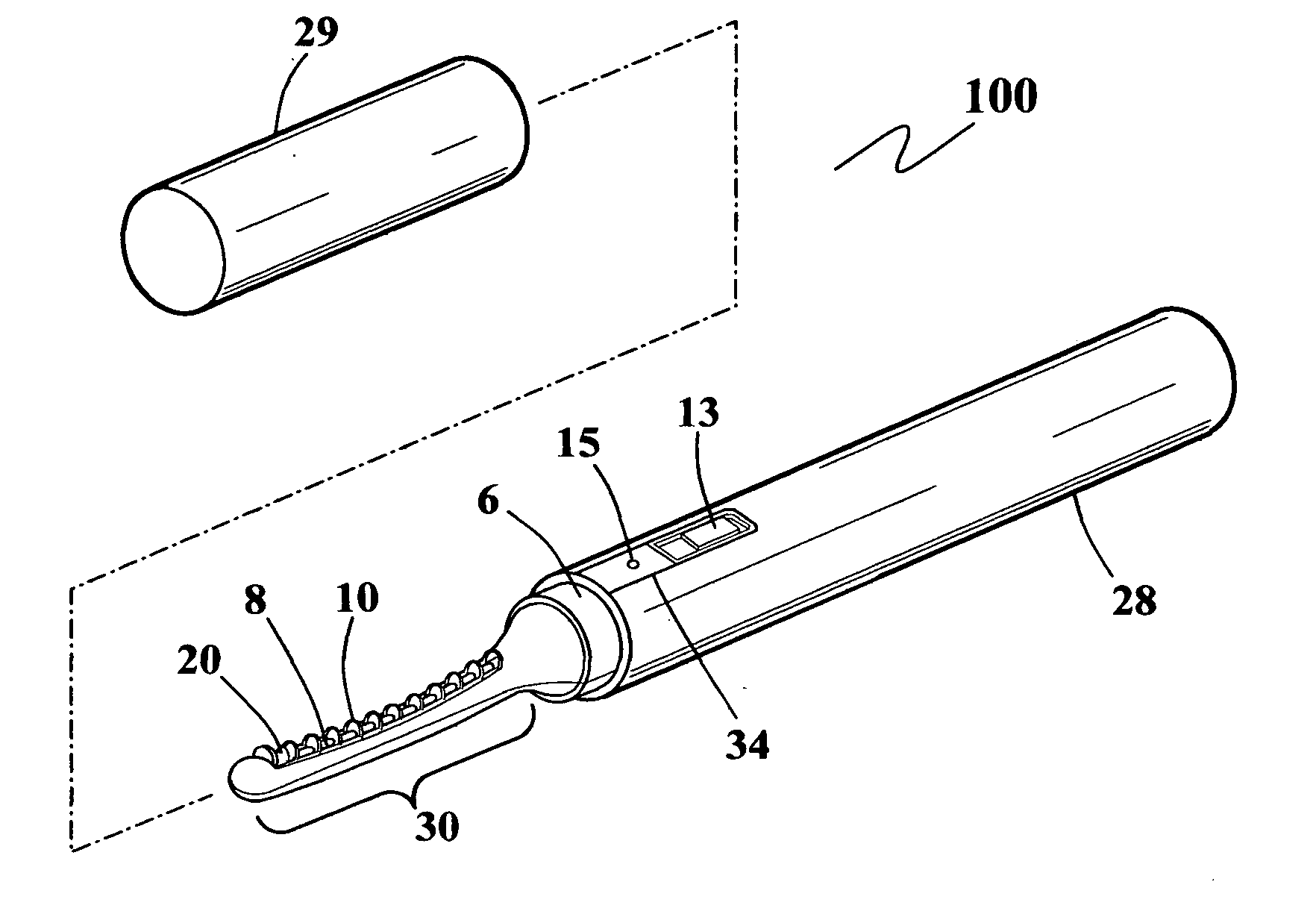
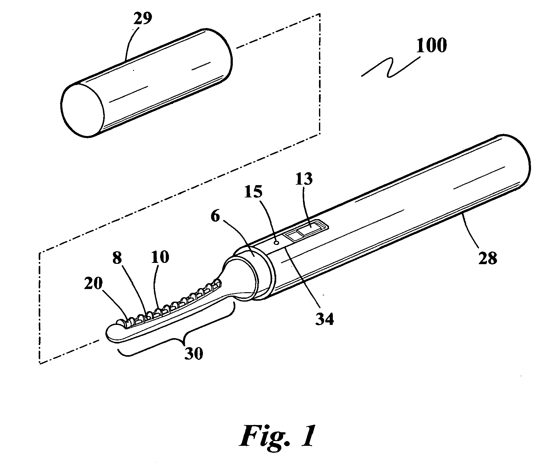
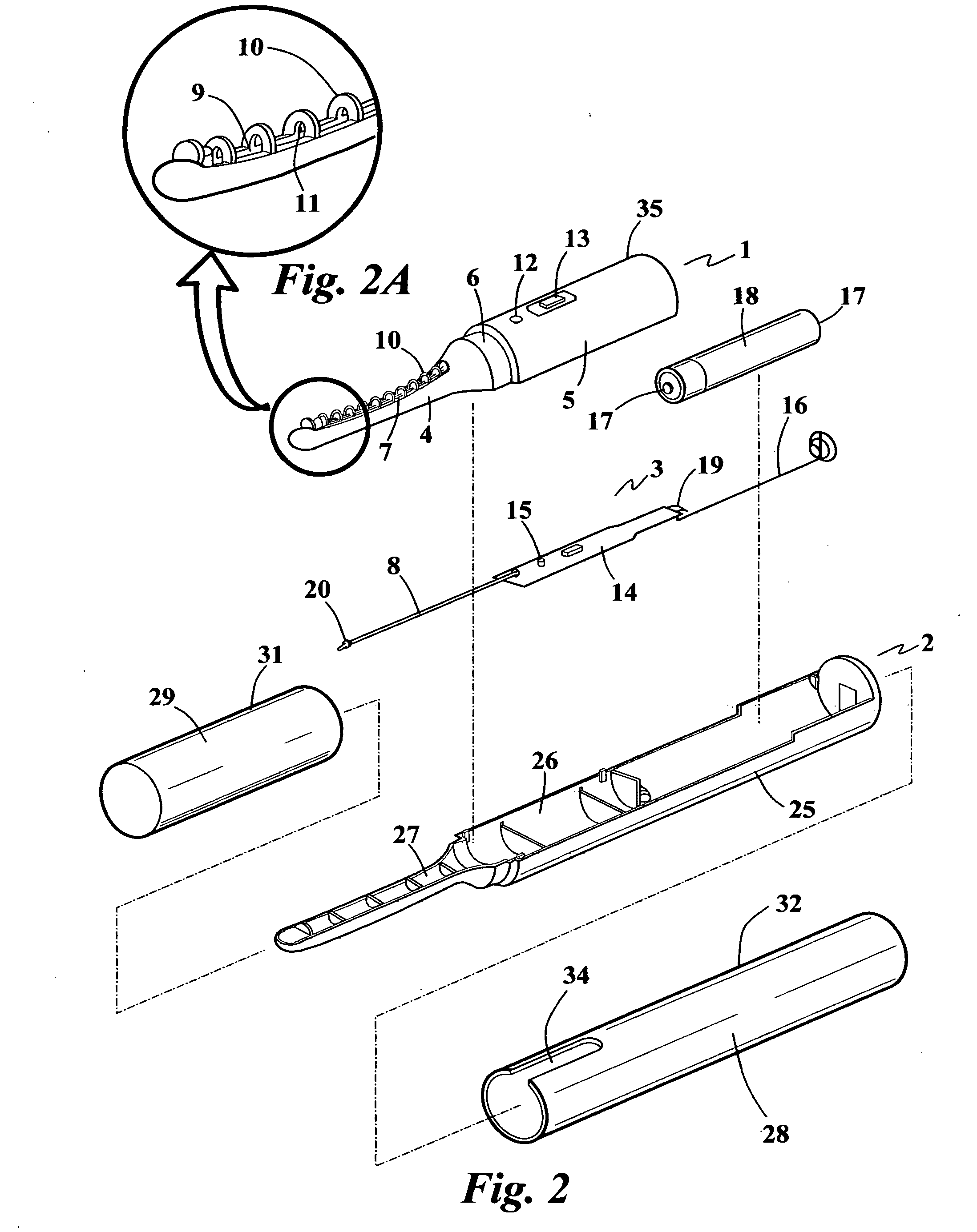
[0020]FIG. 1 shows a perspective view of the heated eyelash curler 100. FIG. 2 shows the parts and an example on how these parts are assembled. The eyelash curler shown on FIG. 2 basically have three major components or parts, an upper casing 1, a lower casing 2 and a middle heater component 3. The middle component 3 is sandwiched between the upper casing 1 and the lower casing 2 before the upper and the lower casing are attached together. [00211 The upper casing includes a head piece 4 and a half cylindrical shaped rear piece 5 with a recessed neck 6 between the head 4 and the rear 5 pieces. The head piece has an arcuate top surface 7 shaped to cause an upward curl after several repeated strokes of the eyelashes on the heating element 8. The arcuate top surface 7 has a slit 9 running horizontally along the head piece where the heating element 8 is introduced to lay above the slit 9. Along the arcuate top surface 7, at the location where the heating element 8 will sit, are a plurali...


PUM


Abstract

A heated eyelash curler comprise a curling head portion having an arcuate top surface on one end and a protection case on the other end. The protection case serves as a handle for the device as well as encloses the power source, for example, a battery. The curling head portion includes a heating element laid on the arcuate top surface caged inside a plurality of bridges or protected between protruding comblike spikes. A pigmented silicone piece which changes in color corresponding to the temperature of the heating element is directly contacted with the heating element for fast and accurate response. The heating element comprises a conducting coil or wire in zigzag configuration inserted into a conducting tube such as a brass tubing coated on the outside surface with a non-sticking material such as teflon. The recommended heating mechanism or circuitry for a battery heated heating element includes a converter for boosting the voltage of the power source. This will hasten the rise in temperature of the heating element and in combination with the heating element having the conducting coil or wire in zigzag configuration, will provide a more stable and even heating.

Description

[0001] This invention relates to a heated eyelash curler. The heating element is uniquely set up to heat evenly and rapidly and is caged inside or between protective shields to prevent the skin from directly touching the heating element as well as protect the girth of the eyes from harm. BACKGROUND [0002] Most eyelash curler shape the eyelashes purely by mechanical pressure by inserting the eyelashes between two pinching elements, mostly arched to conform with the shape of the eyelids. U.S. Pat. No. 6,230,715 proposed the incorporation of a heating element into the pinching elements to hasten the curling process as well as result into a longer lasting curl. In this invention, the eyelashes are curled by a simultaneous application of heat and pressure. As in the current eyelash curlers, the eyelashes are likewise inserted between two pinching elements or forming members having an eyelash-line shape except that a heating member is incorporated into the forming members. The heat is pre...

Claims


Application Information

Patent Timeline
IPC IPC(8): A45D2/48
CPCH05B1/0252A45D2/48
Inventor CHO, YONG HOON
Owner CHO YONG HOON
Why Eureka
Try Eureka