Coil component

a technology of coil components and components, applied in the direction of coil manufacturing, transformer/inductance details, inductance, etc., can solve the problems of failure to secure the mounting strength of the coil component, etc., to achieve the effect of suppressing the degradation of q, and facilitating the sealing of the soldering area

Active Publication Date: 2006-01-12
TDK CORPARATION
View PDF3 Cites 30 Cited by
  • Summary
  • Abstract
  • Description
  • Claims
  • Application Information

AI Technical Summary

Benefits of technology

[0012] In the coil component according to the present invention, each external electrode electrically connected to the lead conductor has the electrode portion formed throughout the direction perpendicular to the axial direction of the coiled conductor on the first side face, whereby it is easier to secure the soldering area than in the coil component described in Laid-Open No. 2002-305111. The outer sheath part will be mechanically connected to a circuit board through the external electrodes throughout the direction perpendicular to the axial direction of the coiled conductor on the first side faces. In consequence of these, it is feasible to secure the mounting strength of the coil component.
[0013] Since the lead conductors have the same width as the coiled conductor, the present invention prevents the lead conductors from inhibiting the flux generated in the coiled conductor, and suppresses the degradation of Q. Since the external electrodes are not substantially formed on the second side face intersecting with the axial direction of the coiled conductor, the flux is not heavily inhibited by the external electrodes.
[0014] Preferably, the outer sheath part further has a third side face parallel to the axial direction of the coiled conductor and adjacent to each first side face, and each of

Problems solved by technology

However, the coil component described in Laid-Open No. 2002-305111 has problems as described below.

Method used


Image

  • Coil component
  • Coil component
  • Coil component

Examples


first embodiment

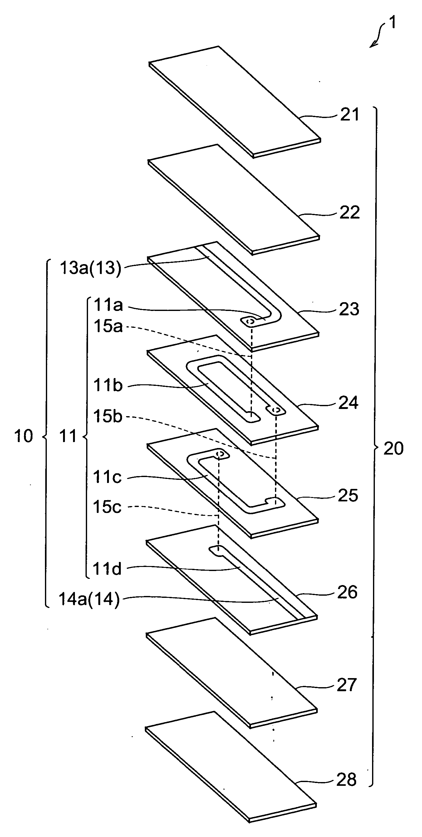
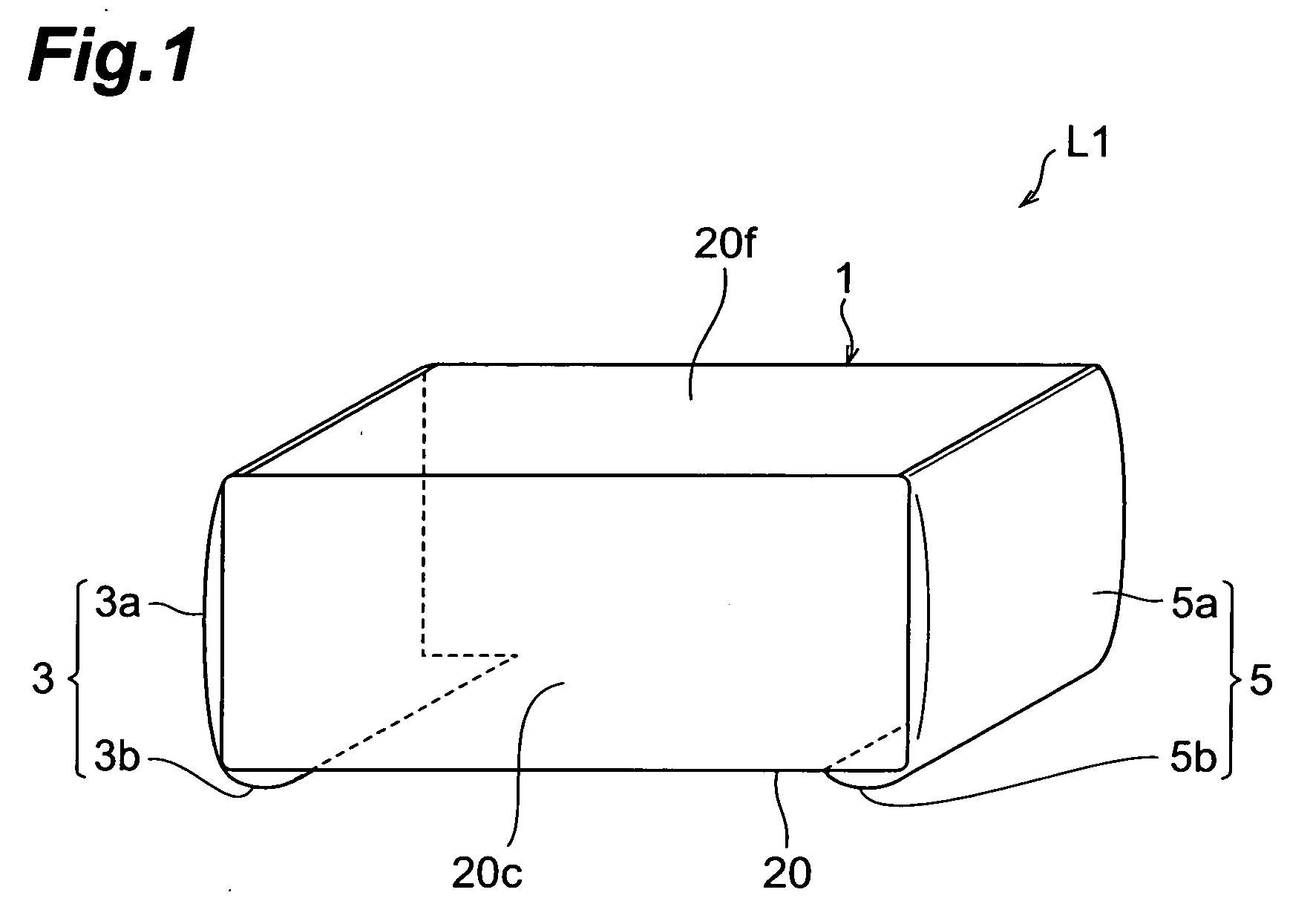
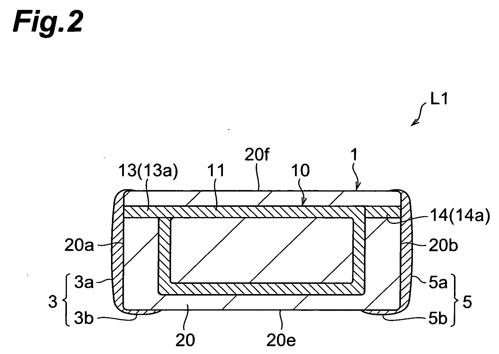
[0033] First, a configuration of a multilayer inductor L1 according to the first embodiment will be described on the basis of FIGS. 1 to 3. FIG. 1 is a perspective view illustrating the multilayer inductor of the first embodiment. FIG. 2 is a view for explaining the sectional configuration of the multilayer inductor of the first embodiment. FIG. 3 is an exploded perspective view illustrating elements included in the multilayer inductor of the first embodiment. FIG. 4 is a perspective view illustrating an outer sheath part included in the multilayer inductor of the first embodiment.

[0034] The multilayer inductor L1, as shown in FIG. 1, is provided with an element 1 of rectangular parallelepiped shape, and a pair of terminal electrodes (external electrodes) 3, 5. The element 1, as shown in FIG. 2, has a coil part 10 and an outer sheath part 20. The coil part 10, as shown in FIG. 3, includes a coiled conductor 11, and lead conductors 13, 14 located at both ends of the coiled conductor...

second embodiment

[0058] First, a configuration of a multilayer inductor L2 according to the second embodiment will be described based on FIGS. 5 and 6. FIG. 5 is a perspective view illustrating the multilayer inductor of the second embodiment. FIG. 6 is a diagram for explaining a sectional configuration of the multilayer inductor of the second embodiment. The multilayer inductor L2 of the second embodiment is different in the configuration of the terminal electrodes 3, 5 from the multilayer inductor L1 of the first embodiment.

[0059] The multilayer inductor L2, as shown in FIG. 5, is provided with an element 1 and a pair of terminal electrodes 3, 5. The element 1, as shown in FIG. 6, has a coil part 10 and an outer sheath part 20.

[0060] Each terminal electrode 3, 5 includes a first electrode portion 3a, 5a, a second electrode portion 3b, 5b, and a third electrode portion 3c, 5c which are electrically continuous to each other. The third electrode portion 3c, 5c is formed on a part of the fourth side...


PUM


Abstract

A multilayer inductor is provided with a coil part including a coiled conductor and lead conductors, an outer sheath part covering the coil part and having an electrical isolation, and external electrodes electrically connected to the respective lead conductors. The lead conductors are located at both ends of the coiled conductor and have a width identical with that of the coiled conductor. The outer sheath part has two first side faces parallel to the axial direction of the coiled conductor and not adjacent to each other, and a second side face intersecting with the axial direction of the coiled conductor. Each external electrode has a first electrode portion formed throughout a direction perpendicular to the axial direction of the coiled conductor on the first side face. Each external electrode is not substantially formed on the second side face.

Description

BACKGROUND OF THE INVENTION [0001] 1. Field of the Invention [0002] The present invention relates to a coil component. [0003] 2. Related Background Art [0004] An example of the known coil components of this type is the one as described in Japanese Patent Application Laid-Open No. 2002-305111, which comprises a coil part including a coiled conductor, and lead conductors located at both ends of the coiled conductor, an outer sheath part covering the coil part, and a plurality of external electrodes electrically connected to the respective lead conductors. [0005] The coil component described in Laid-Open No. 2002-305111 is a multilayer inductor. In this multilayer inductor, electrically insulating layers and conductor patterns are alternately stacked and ends of the respective conductor patterns are successively connected to form a coil (coiled conductor) superimposed in the stack direction in an electric insulator body (outer sheath part). The ends of the coil are connected through th...

Claims


Application Information

Patent Timeline
IPC IPC(8): H01F5/00
CPCH01F17/0013H01F41/10H01F27/292
Inventor TOZAWA, YOJISATO, HIDEKAZUKAWASAKI, KUNIHIKOMOCHIZUKI, YOSHINORIOKAMOTO, SATORUSASAKI, KOUZOUISHIFUNE, MICHIRUSATO, SHINICHIABE, KATSUMIKUMAGAI, SHUUMI
Owner TDK CORPARATION
Why Eureka
Try Eureka