Body mounted LED-based anti-collision light for aircraft

an anti-collision light and led-based technology, applied in the field of aircraft anti-collision lights, can solve the problems of red leds experiencing a much higher level of degradation, increasing size, and increasing so as to simplify thermal management, reduce the number of leds, and reduce the cost and power consumption

Active Publication Date: 2006-01-12
HONEYWELL INT INC
View PDF27 Cites 75 Cited by
  • Summary
  • Abstract
  • Description
  • Claims
  • Application Information

AI Technical Summary

Benefits of technology

[0018] According to an exemplary embodiment, the rotationally symmetrical configuration of the LEDs in the anti-collision light includes two rings of LEDs. In an exemplary embodiment, the anti-collision light further includes a reflector system that redistributes light from at least one of the LED rings into a pattern that satisfies the photometric distribution specified in the FARs. The use of a reflector system may reduce the number of LEDs used in the anti-collision device, thereby reducing costs and power consumption, while simplifying thermal management.

Problems solved by technology

Also, in Xenon-based anti-collision lights, providing both visible and covert (infrared) capabilities generally causes the package size to grow.
Such dual-mode capability causes the increase in size because infrared (IR) sources cannot be mounted in the same envelope as the Xenon flash tube.
Red LEDs experience a much higher level of degradation when operated near their maximum allowable junction temperature.
However, synchronizing flashing anti-collision lights on an aircraft with wild frequency power presents certain challenges.

Method used


Image

  • Body mounted LED-based anti-collision light for aircraft
  • Body mounted LED-based anti-collision light for aircraft
  • Body mounted LED-based anti-collision light for aircraft

Examples


Embodiment Construction

[0034] Exemplary embodiments of the present invention are described in the following description.

[0035] Given that the photometric requirements of the Federal Aviation Regulations (FARs) for anti-collision lights are rotationally symmetrical, exemplary embodiments of the present invention utilize an optical approach, which is also rotationally symmetrical.

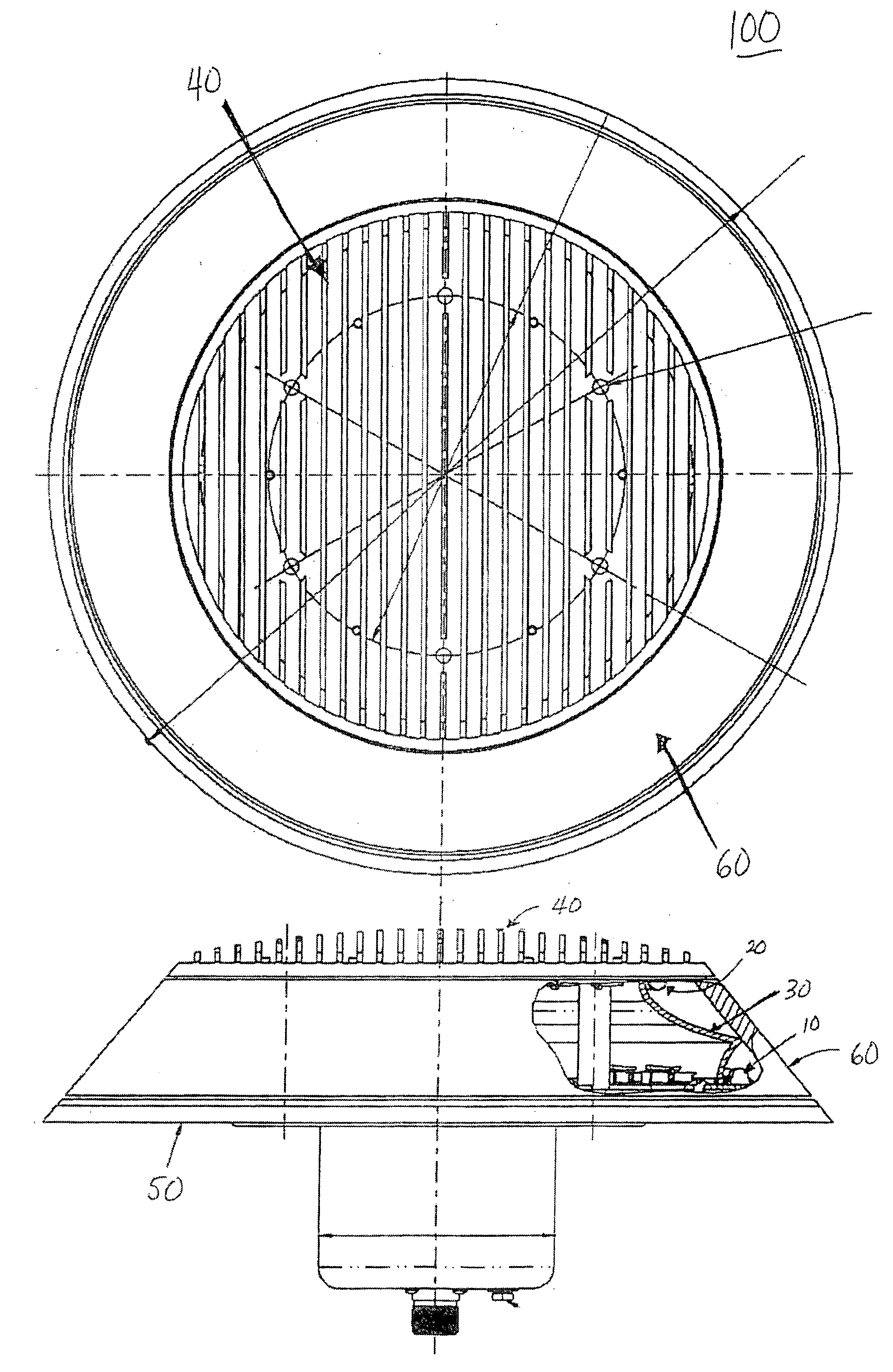
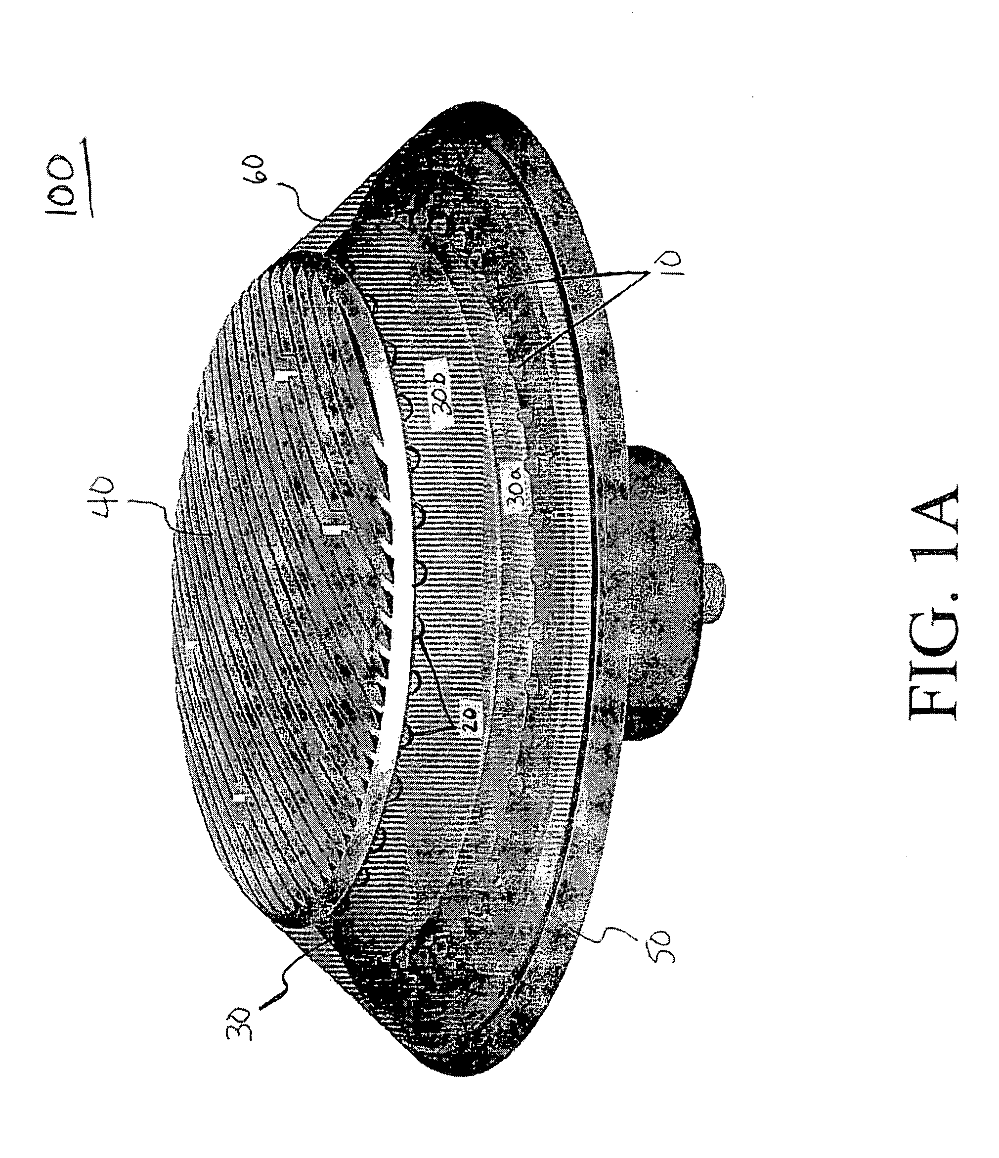
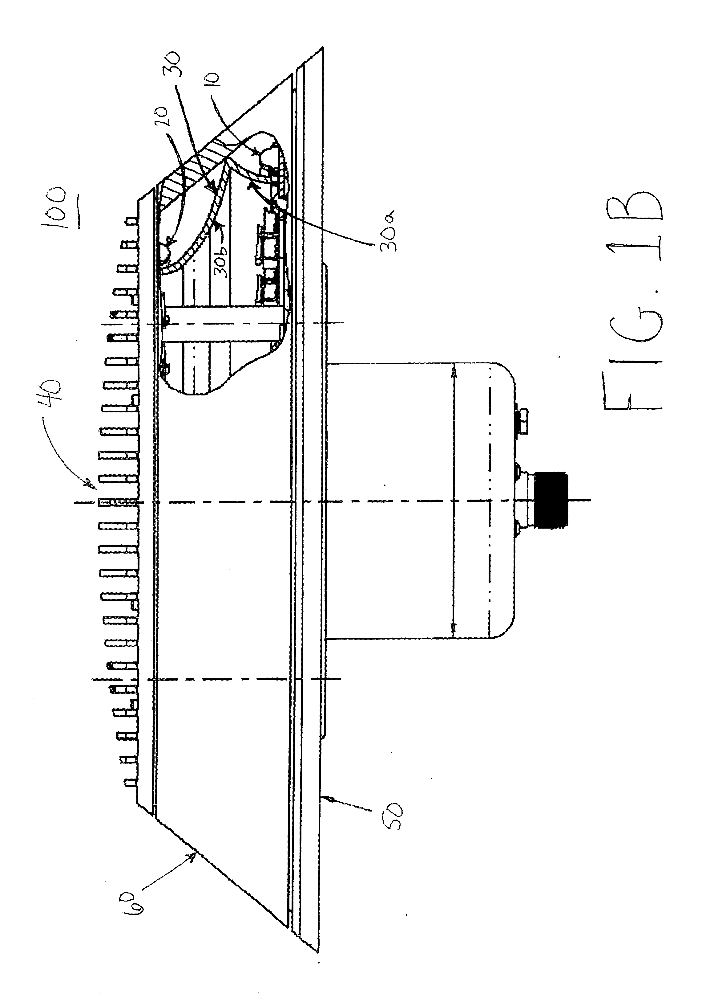
[0036]FIGS. 1A and 1B illustrate a fuselage-mounted anti-collision light, according to an exemplary embodiment of the present invention. In the anti-collision light 100 of this embodiment, a first ring of LEDs 10 are mounted along the perimeter of a base portion 50 (or “base platform”). A second ring of LEDs 20 are inverted and attached to a top portion 40 (“top platform”) of the anti-collision light 100. In an exemplary embodiment, the first and second rings of LEDs 10 and 20 may be substantially arranged in a rotationally symmetric manner (i.e., symmetrical about a vertical axis).

[0037] According to an exemplary embodiment, th...


PUM


Abstract

A rotationally symmetrical anti-collision light (100, 200) for an aircraft utilizing light-emitting diodes (LEDs) is mounted to the fuselage of an aircraft. The LEDs (10, 10′, 20, 20′) may be configured in one or more concentric rings. The anti-collision light includes a reflector (30, 30′) configured to redirect the light emitted by at least one of the rings, so that the light pattern satisfies predetermined specifications.

Description

CROSS-REFERENCES TO RELATED APPLICATIONS [0001] This Nonprovisional application claims priority under 35 U.S.C. § 119(e) on U.S. Provisional Application No. 60 / 585,529 filed on Jul. 6, 2004, the entire contents of which are hereby incorporated by reference.FIELD OF THE INVENTION [0002] The present invention is directed to aircraft anti-collision lights and, more particularly, to aircraft anti-collision lights utilizing light-emitting diodes (LEDs). BACKGROUND [0003] Existing anti-collision lights utilize Xenon flash tube technology. However, anti-collision lights using LEDs are advantageous because of their longer lives, lower power consumption, and reduced weight (because a separate power supply is not needed) compared to Xenon-based systems. [0004] Also, in Xenon-based anti-collision lights, providing both visible and covert (infrared) capabilities generally causes the package size to grow. Such dual-mode capability causes the increase in size because infrared (IR) sources cannot ...

Claims


Application Information

Patent Timeline
Patent Type & Authority Applications(United States)
IPC IPC(8): G08B5/22B64D47/06F21W107/30
CPCB64D47/06F21V7/0008F21V7/0058F21W2101/06B64D2203/00F21Y2103/022H05B33/0893H05B37/038F21Y2101/02F21Y2103/33F21Y2115/10F21W2107/30H05B45/58H05B47/235
Inventor MACHI, NICOLO F.SINGER, JEFFREY M.BARNHART, BRIAN J.
Owner HONEYWELL INT INC
Why Eureka
Try Eureka