Apparatus and method for driving liquid crystal display device

a liquid crystal display and apparatus technology, applied in the direction of identification means, instruments, optics, etc., can solve the problems of large power consumption and inability to realize partial peak brightness

Inactive Publication Date: 2006-01-12
LG DISPLAY CO LTD
View PDF12 Cites 63 Cited by
  • Summary
  • Abstract
  • Description
  • Claims
  • Application Information

AI Technical Summary

Benefits of technology

[0029] According to an aspect of the invention, there is an apparatus for driving a liquid crystal display device, the apparatus comprising: a liquid crystal display panel having at least two division areas; a light generator including at least one light emitting diode (LED) and irradiating light to each division area of the liquid crystal display panel; and a driver to control a brightness of the light emitted by the LED and irradiating to each division area, in accordance with a peak value of gray level of each division area.
[0030] According to an aspect of the invention, there is a liquid crystal display device comprising: a liquid crystal display panel; a backlight unit including a plurality of light emitting diodes (LEDs) to irradiating light to the liquid crystal display panel; and a driver to selectively drive the LEDs and selectively control a brightness of light generated by the LEDs.

Problems solved by technology

However, the related art LCD has disadvantages in that it needs to have the lamps turned on continuously, whereby its power consumption is large and a partial peak brightness cannot be realized.

Method used


Image

  • Apparatus and method for driving liquid crystal display device
  • Apparatus and method for driving liquid crystal display device
  • Apparatus and method for driving liquid crystal display device

Examples


first embodiment

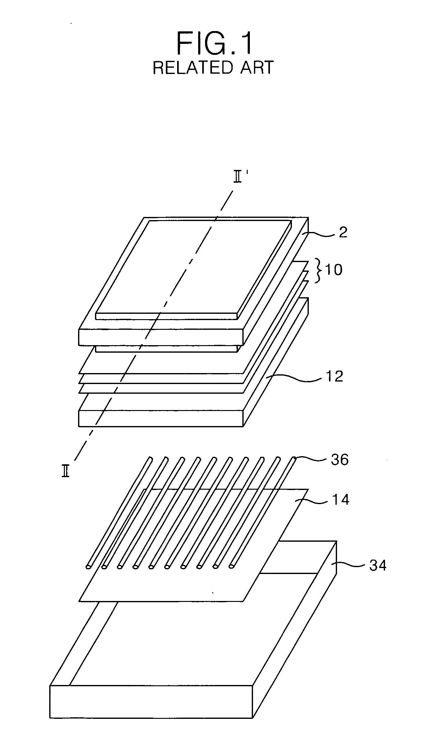
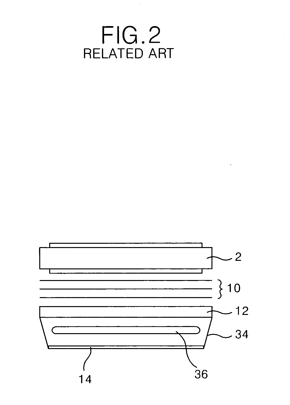
[0047]FIG. 3 is a perspective view illustrating a liquid crystal display device according to the present invention.

[0048] Referring to FIGS. 3 and 4, a liquid crystal display device according to the first embodiment of the present invention includes: a liquid crystal display panel 102 to display a picture or image; a backlight unit having a plurality of white light emitting diodes LEDs 136 to irradiate a white light to each designated area of the liquid crystal display panel 102; and at least one LED driver 160 to drive each of the white LEDs 136. All the components of the liquid crystal display device are operatively coupled.

[0049] In the liquid crystal display panel 102, liquid crystal cells are arranged between an upper substrate and a lower substrate in a manner of an active matrix type, and a common electrode and pixel electrodes to apply electric field to each of the liquid crystal cells are provided. Generally, the pixel electrode is formed on the lower substrate, i.e., a th...

second embodiment

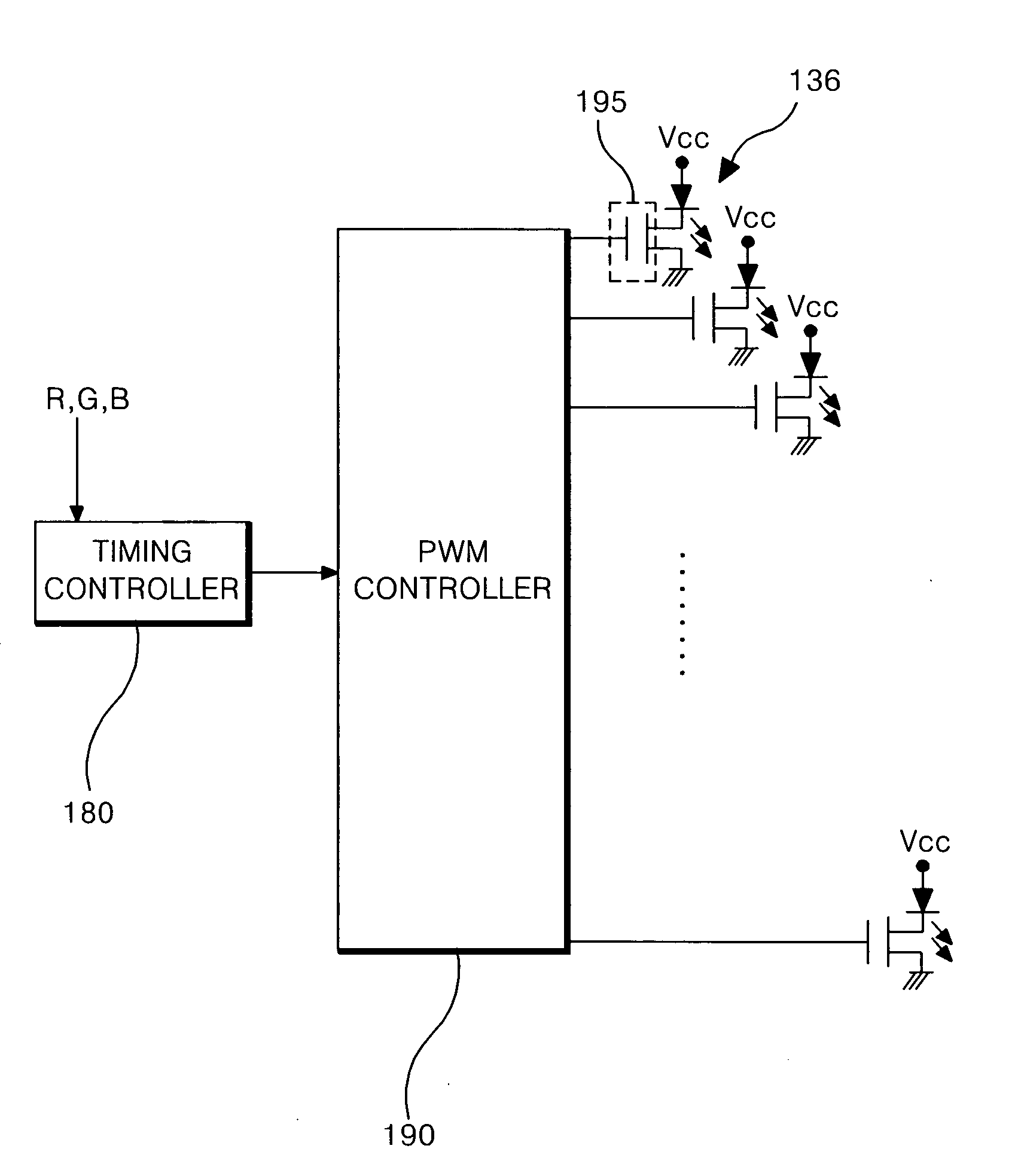
[0070]FIG. 10 is a perspective view illustrating a driving apparatus of a liquid crystal display device according to the present invention.

[0071] The driving apparatus of the liquid crystal display device according to the second embodiment of the present invention includes: a liquid crystal display panel 202 to display a picture; a backlight unit having a plurality of red, green, and blue LEDs (RGB LEDs) 236 to irradiate light onto each designated area of the liquid crystal display panel 202; at least one LED driver 260 to drive each of the RGB LEDs 236. All the components of the liquid crystal display device including the driving apparatus are operatively coupled.

[0072] The structure and functions of the elements of the driving apparatus in the second embodiment of the present invention are identical to those of the first embodiment, except for the RGB LEDs 236 and the LED driver 260. Thus, the detailed description on the identical elements will be omitted for the sake of simple i...


PUM

PropertyMeasurementUnit
wavelengthaaaaaaaaaa

Abstract

An apparatus and method for driving a light source of a liquid crystal display device are provided. The apparatus includes a liquid crystal display panel, a backlight unit including a plurality of light emitting diodes (LEDs) to irradiating light to the liquid crystal display panel, and a driver to selectively drive the LEDs and selectively control a brightness of light generated by the LEDs.

Description

[0001] This application claims the benefit of Korean Patent Application No. 10-2004-0038420 filed in Republic of Korea on May 28, 2004, which is hereby incorporated by reference. BACKGROUND OF THE INVENTION [0002] 1. Field of the Invention [0003] The present invention relates to an apparatus and a method for driving a liquid crystal display device, and more particularly, to an apparatus and a method for driving a lamp of a liquid crystal display device that is capable of controlling a partial brightness and a color character. [0004] 2. Description of the Related Art [0005] In general, a liquid crystal display (hereinafter, LCD) has a trend that its application scope has been gradually widened due to its lightness, its thinness, and its low power consumption. In accordance with such a trend, the LCD is used in an office automation device, an audio / video device and the like. The LCD adjusts the transmittance quantity of a light beam in accordance with an image signal applied to a matr...

Claims


Application Information

Patent Timeline
Patent Type & Authority Applications(United States)
IPC IPC(8): G09G3/36G02F1/133G02F1/13357G09F9/35G09G3/20G09G3/34
CPCG02F1/133603G02F2201/52G09G2320/064G09G3/3426G09G2320/0633G09G3/3413G02F1/133
Inventor OH, EUI YEOLHONG, HEE JUNGKIM, HONG CHULPARK, HEE JEONG
Owner LG DISPLAY CO LTD
Why Eureka
Try Eureka