Multi-camera inspection of underwater structures

a multi-camera, underwater technology, applied in the direction of image analysis, scene recognition, instruments, etc., can solve the problems of human involvement being unsafe, the process of underwater search and inspection in the context of security and risk containment has proved too dangerous for direct human involvement, and other serious complexities in the computer processing and analysis of video can aris

Inactive Publication Date: 2006-01-12
MIAMI UNIVERISTY OF
View PDF7 Cites 53 Cited by
  • Summary
  • Abstract
  • Description
  • Claims
  • Application Information

AI Technical Summary

Problems solved by technology

Yet, the process of underwater search and inspection in the context of security and risk containment has proven too dangerous for direct human involvement.
In particular, the potential presence of hazardous and deadly materials has proven human involvement to be unsafe and requires the use of submersible robotics platforms to avoid risking human lives.
While the absence of natural lighting at depth can pose serious challenges in deep sea operations, other serious complexities in the computer processing and analysis of the video can arise in shallow waters in the course of performing automated inspection.
Such complexities can include those which arise due to non-uniform moving shadows cast by surface waves, floating suspended particles, and the like.
The fundamental problem is to estimate the frame-to-frame motions of the camera from the corresponding pair of images.
In deep sea, these are induced by the motion of artificial sources with limited power.
In addition, other complexities arise from the movement of floating suspended particles and water bubbles that are commonly present in shallow waters.
While the pitch and roll states theoretically can be determined from video, the estimation is seldom robust and accurate particularly where the target scene (seafloor) is relatively flat.
That is, where the topographical variations are small compared to the distance to the sea floor, it can be difficult to estimate the pitch and roll states of the visual servo.
Unfortunately, the heading change cannot be reliably measured from typically compasses due to magnetic masking near the ship.

Method used


Image

  • Multi-camera inspection of underwater structures
  • Multi-camera inspection of underwater structures
  • Multi-camera inspection of underwater structures

Examples


Embodiment Construction

[0024] I. Introduction

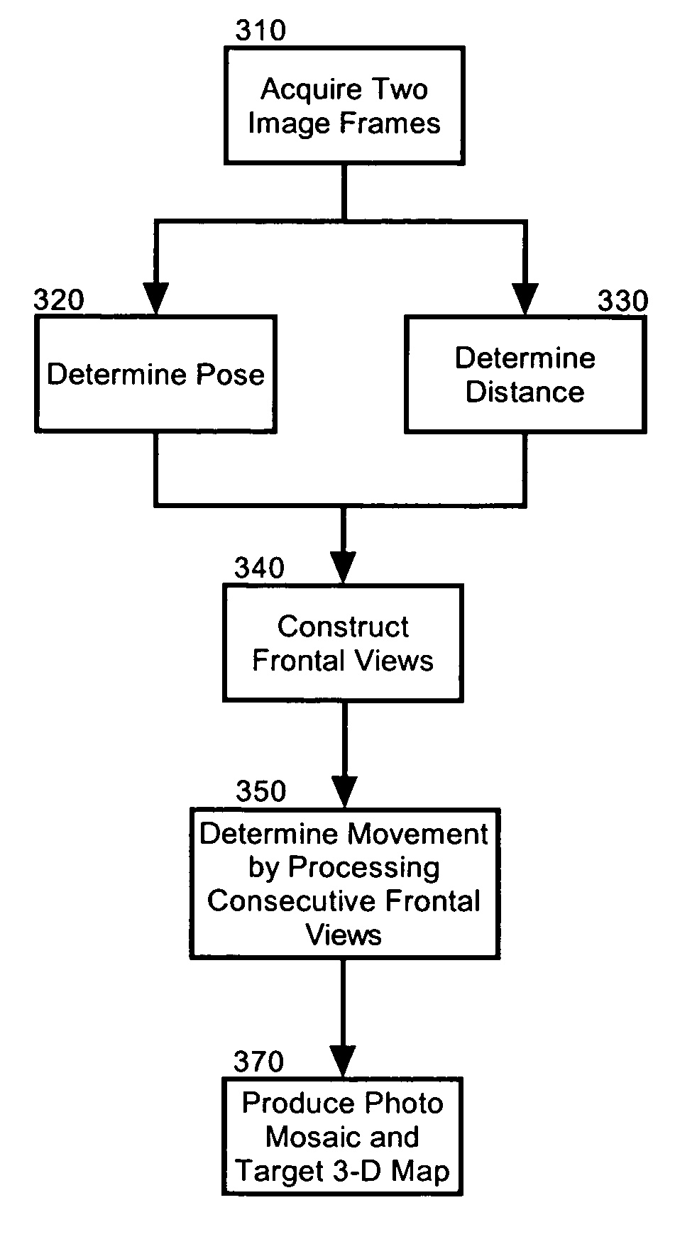
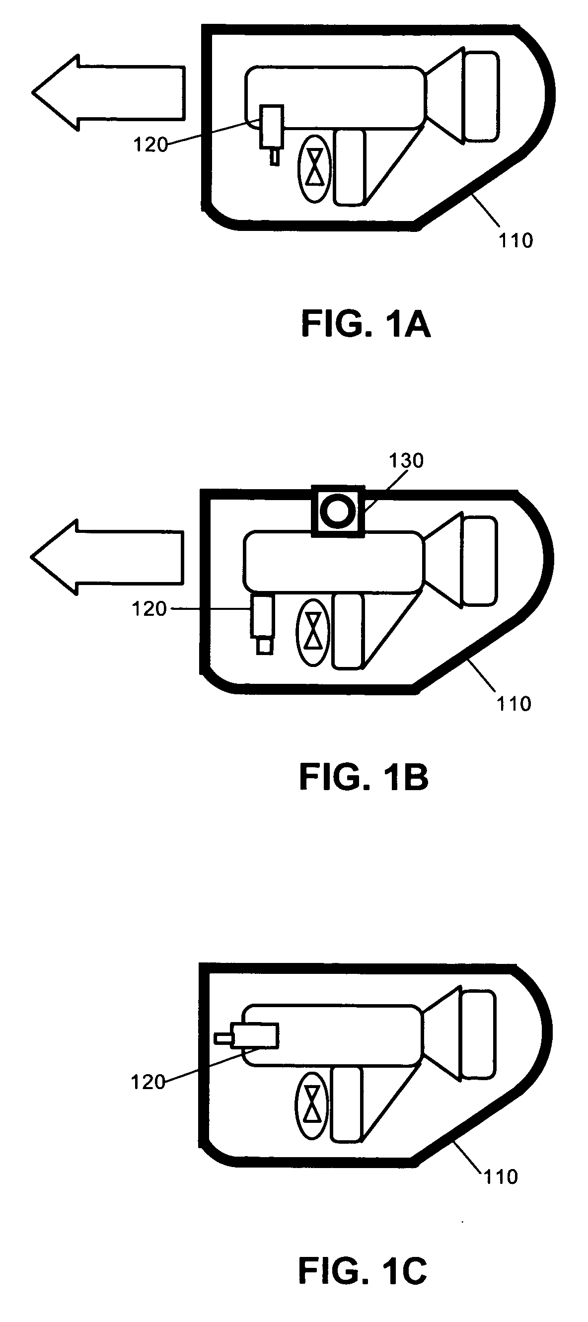
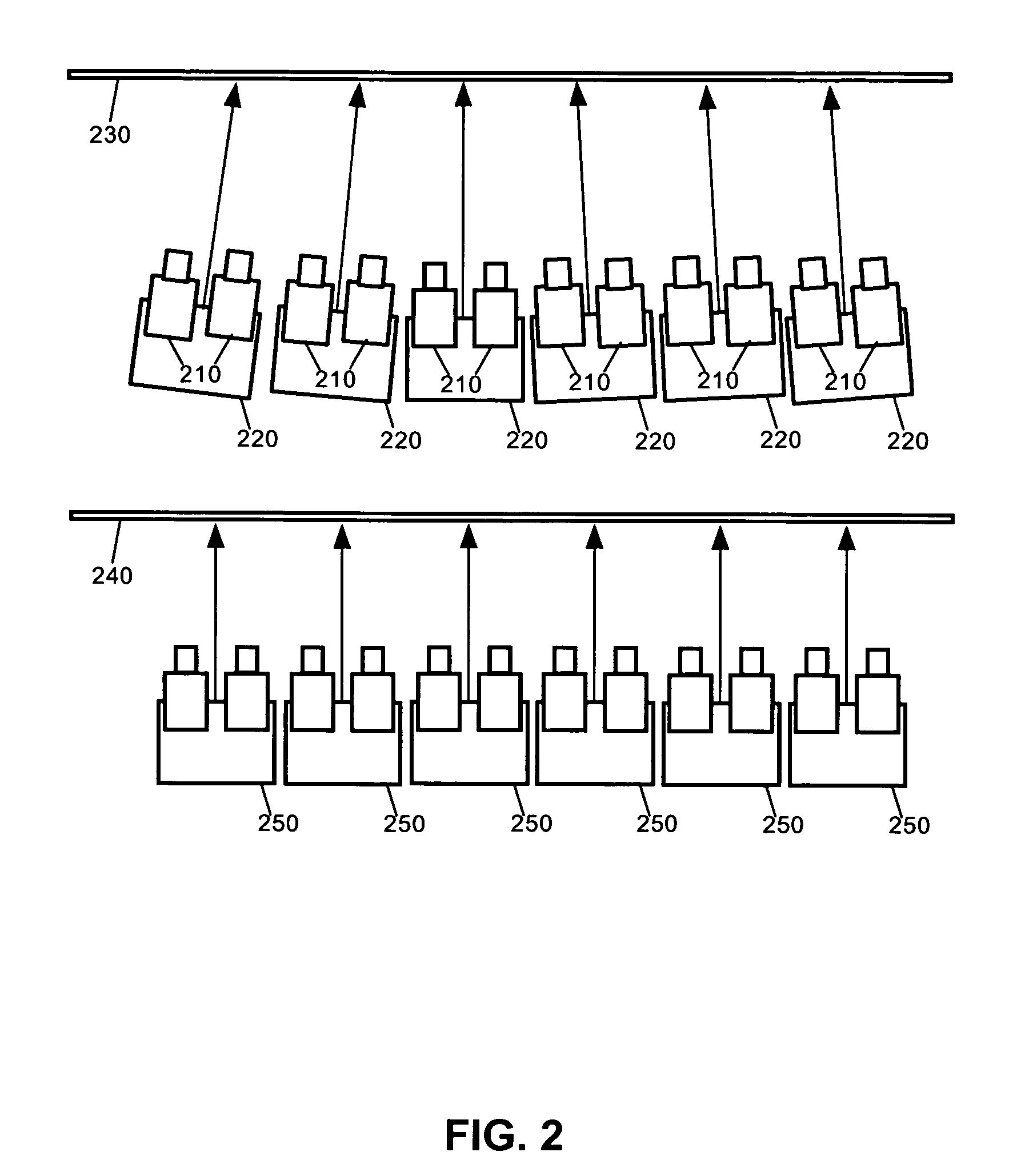
[0025] The present invention is a multi-camera vision system for automated or operator-assisted inspection of underwater structures. The system of the present invention can include a stereovision system for precise positioning and navigation. The stereovision system can perform precise positioning and navigation by estimating the six degrees of freedom in the movement of a submersible platform directly from acquired images. In this regard, the stereo imagery can provide direct measurements of the distance and orientation with respect to the structure, which subsequently can be used to control the trajectory of the platform. The stereo processing performance can be optimized to take advantage of the relatively flat shape of target surfaces at arbitrary orientations, including hull surfaces, dams and docks. The information regarding the motion of the platform, determined from consecutive stereo imagery, also can be used for image or target three-dimensional (3-D...


PUM


Abstract

A method, system and apparatus for viewing and imaging an underwater structure from a submersible platform, navigating along the structure and constructing a map of the structure in the forms of a photo-mosaic and a 3-D structural map. The system can include a submersible platform, at least two cameras coupled to the submersible platform, and stereovision matching logic programmed to simulate a frontal view of a target underwater structure from a fixed distance based upon an oblique view of the target underwater structure obtained by the cameras from a variable distance. The cameras can be forward or side mounted to the submersible platform and can include optical cameras, acoustical cameras or both. Preferably, the submersible platform can be a remotely operated vehicle (ROV), or an autonomous underwater vehicle (AUV). Finally, the system further can include absolute positioning sensors.

Description

CROSS-REFERENCE TO RELATED APPLICATIONS [0001] This patent application claims the benefit under 35 U.S.C. § 119(e) of presently pending U.S. Provisional Patent Application 60 / 504,330, entitled ROV-BASED SHIP HULL INSPECTION, filed on Sep. 19, 2003, the entire teachings of which are incorporated herein by reference.STATEMENT REGARDING FEDERALLY SPONSORED RESEARCH [0002] The government of the United States of America has rights in this invention pursuant to grant number N000140310074-02 by the United States Department of Defense Office of Naval Research to the University of Miami.FIELD OF THE INVENTION [0003] The present invention relates to the visual inspection of an underwater structure such as a ship hull, and more particularly to a vision system for use in the automated and human-assisted inspection of underwater structures. BACKGROUND OF THE INVENTION [0004] In-water inspection is an essential task in the general maintenance and damage assessment of underwater structures. For ex...

Claims


Application Information

Patent Timeline
Patent Type & Authority Applications(United States)
IPC IPC(8): G06K9/00G01CG06V10/147G06V20/13
CPCG06K9/0063G06K9/209G06T7/0075G06T7/0044G06K2009/2045G06T7/74G06T7/593G06V20/13G06V10/16G06V10/147
Inventor NAGAHDARIPOUR, SHAHRIARFIROOZFAM, PEZHMAN
Owner MIAMI UNIVERISTY OF
Why Eureka
Try Eureka