Anti-backup mechanism for repeating multi-clip applier

a multi-clip applier and anti-backup technology, applied in the field of surgical clip appliers, can solve problems such as clip appliers, and achieve the effect of preventing double loading of clips

Inactive Publication Date: 2006-01-12
BLAKE JOSEPH W III +1
View PDF7 Cites 212 Cited by
  • Summary
  • Abstract
  • Description
  • Claims
  • Application Information

AI Technical Summary

Benefits of technology

[0010] Another object of the invention is to provide a clip applicator having an operating handle with an anti-backup mechanism that permits full forward and reverse strokes of a clip applying cartridge to avoid the hazard of releasing a partially crimped clip at a surgical site.
[0011] Anoth

Problems solved by technology

A well-known hazard with clip appliers is a condition o

Method used


Image

  • Anti-backup mechanism for repeating multi-clip applier
  • Anti-backup mechanism for repeating multi-clip applier
  • Anti-backup mechanism for repeating multi-clip applier

Examples


Embodiment Construction

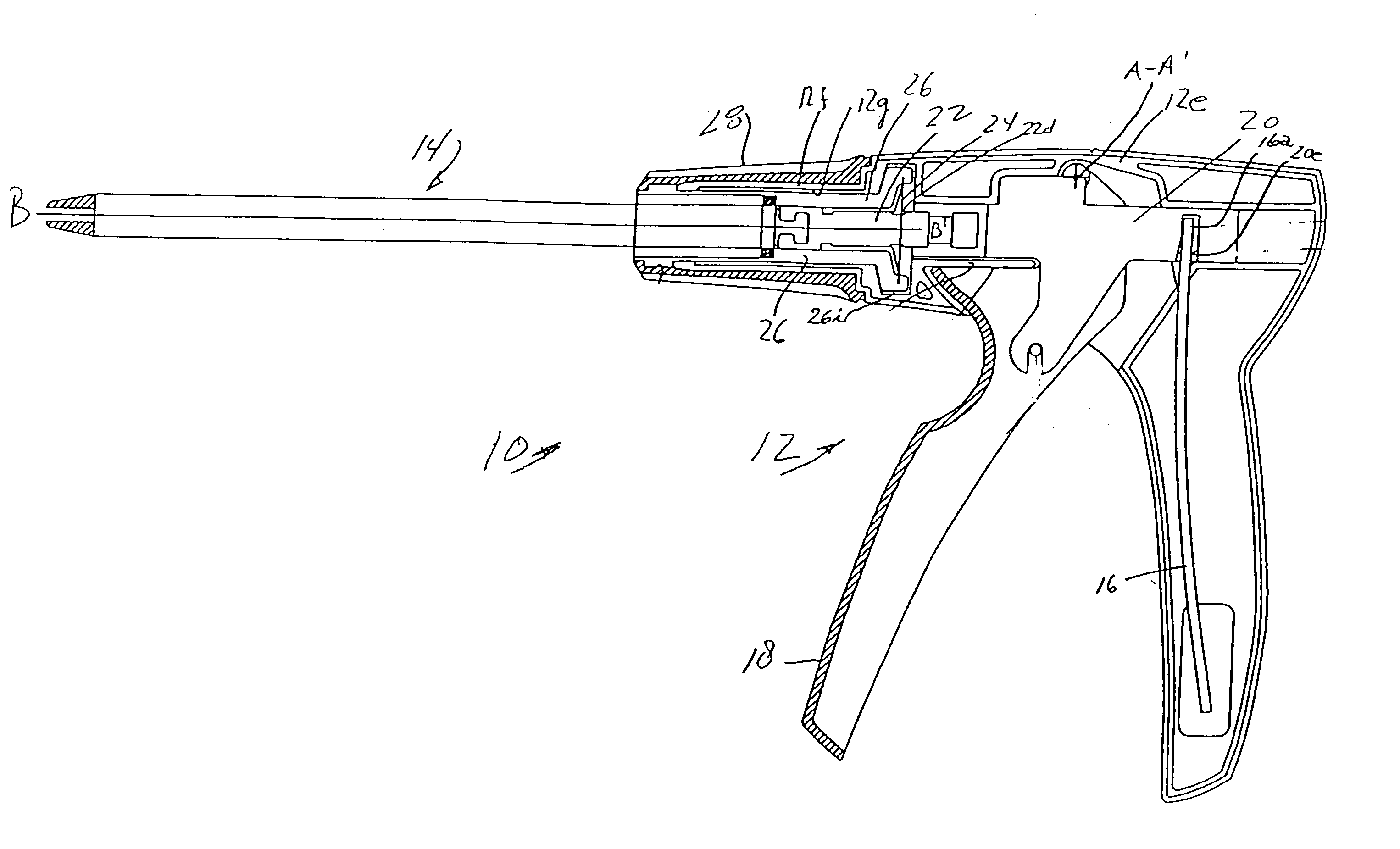
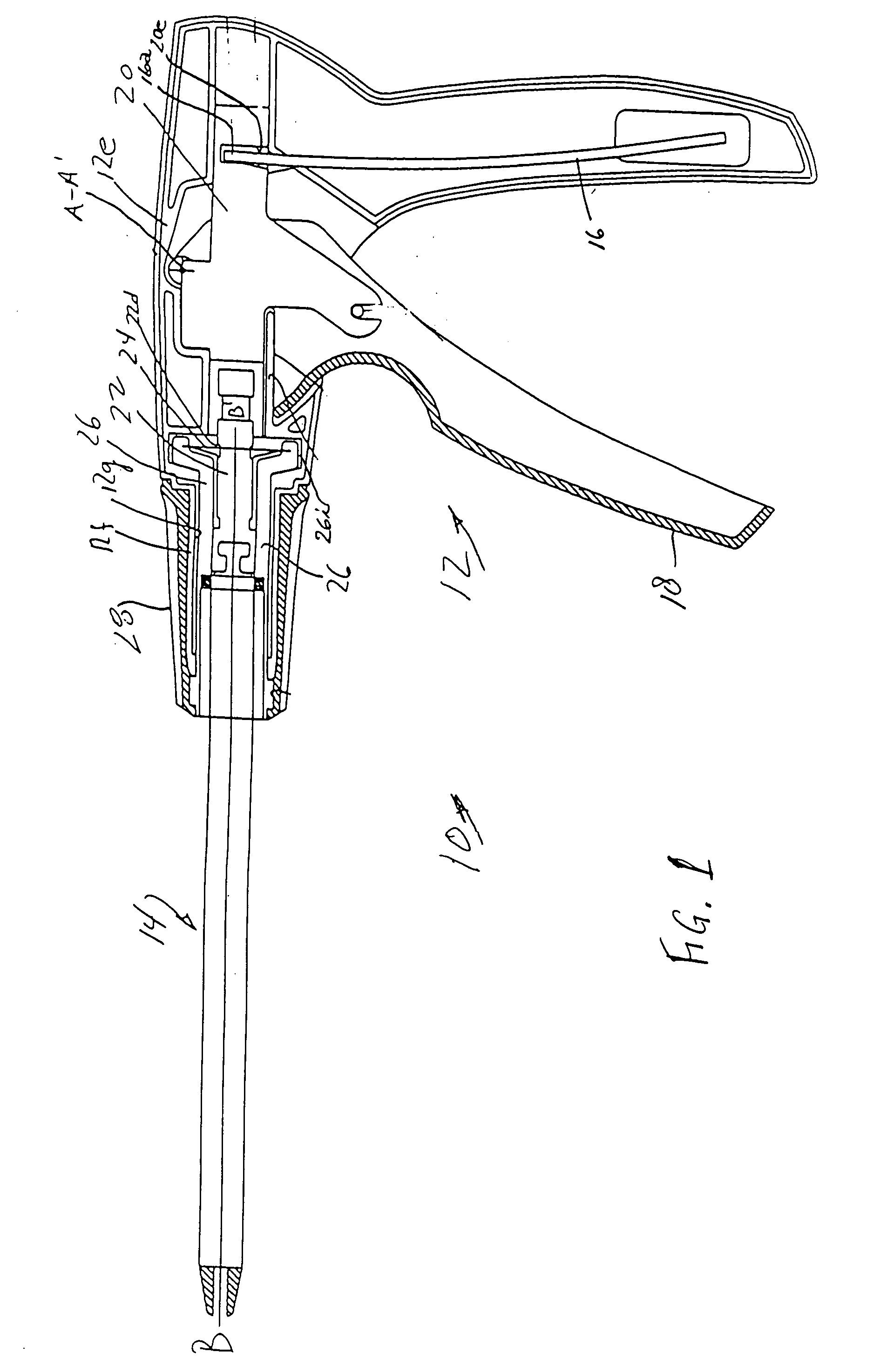
[0021] Referring to the drawing, a preferred embodiment of the repeating multi-clip applier 10 comprises operating handle housing 12 and clip applicator cartridge 14.

[0022] The operating handle housing 12 shown in FIGS. 1-2 comprises handle members including a depending grip 12c, a center section defining a central chamber 12e, and a forward cylindrical portion 12f defining a forward chamber 12g.

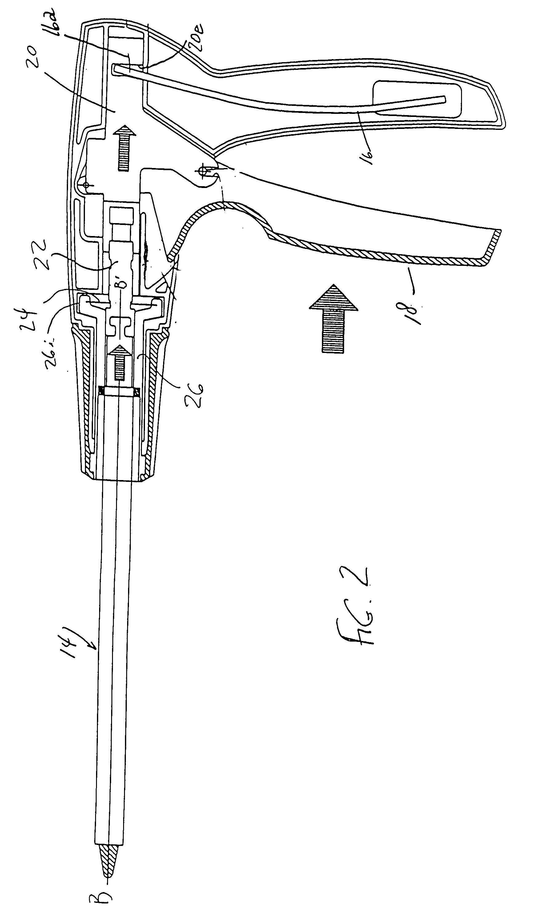
[0023] A trigger 18 for actuating applier mechanisms is mounted on the housing for pivotal movement about axis A-A′, normal to FIG. 1. The trigger includes a depending grip portion 18.

[0024] The trigger when pulled transmits motion to the clip cartridge mechanism (not shown) through the intermediation of fixed translator slide 20 and a rotary translator 22. The trigger acts against the forward bias of bar spring 16 with its end 16a held by translator slide recess 20a.

[0025] The rotary translator 22 (FIGS. 1, 2, and 3) forms a subassembly with an anti-backup mechanism 24, a rotatable drum...


PUM


Abstract

An instrument for applying clips in surgery having an operating handle with operating components and a clip cartridge with clip applying mechanism. The handle operating components generate reciprocal linear motion imparted to the clip applying mechanism and accommodate rotation of the cartridge about a cartridge axis. An anti-backup mechanism constrains operating components to complete first and second strokes of reciprocal linear motion.

Description

PRIOR APPLICATION [0001] This application is a division of U.S. patent application Ser. No. 10 / 315,969 filed Dec. 10, 2002, now abandoned.BACKGROUND OF THE INVENTION [0002] The present invention relates to surgical clip appliers embodied as an instrument having a supply of clips for rapidly deploying several clips in closing severed blood vessels and other small fluid carrying ducts in surgical procedures. There are many different designs for surgical clip applicators for a variety of surgical procedures including both open surgery and laparoscopy in which a clipping appliance fits through a trocar tube into a body cavity where the clips are applied. [0003] A surgical clip applicator comprises an operating handle and clip applying mechanism having an operating cycle in which operating levers are squeezed together and released. In this operating cycle, a clip is applied in surgery and the clip applicator jaws are reloaded with a single clip from a clip supply channel for clip applica...

Claims


Application Information

Patent Timeline
IPC IPC(8): A61B17/10A61B17/00A61B17/128A61L
CPCA61B17/128A61B2017/2929A61B2017/00367A61B17/1285
Inventor BLAKE, JOSEPH W. IIILISK, KENNETH J.
Owner BLAKE JOSEPH W III
Why Eureka
Try Eureka