Methods and apparatus for using water use signatures and water pressure in improving water use efficiency

a technology of water use signatures and water pressure, applied in the direction of apparatus for force/torque/work measurement, fluid tightness measurement, machines/engines, etc., can solve the problems of not being able to give information back to individuals nor use feedback, and many individuals may not be aware of leakage in water lines or irrigation systems, etc., to achieve the effect of reducing was

a technology of water use signatures and water pressure, applied in the direction of apparatus for force/torque/work measurement, fluid tightness measurement, machines/engines, etc., can solve the problems of not being able to give information back to individuals nor use feedback, and many individuals may not be aware of leakage in water lines or irrigation systems, etc., to achieve the effect of reducing was

US20060009928A1Inactive Publication Date: 2006-01-12AQUA CONSERVATION SYST

Image

  • Methods and apparatus for using water use signatures and water pressure in improving water use efficiency
  • Methods and apparatus for using water use signatures and water pressure in improving water use efficiency
  • Methods and apparatus for using water use signatures and water pressure in improving water use efficiency

Examples


Embodiment Construction

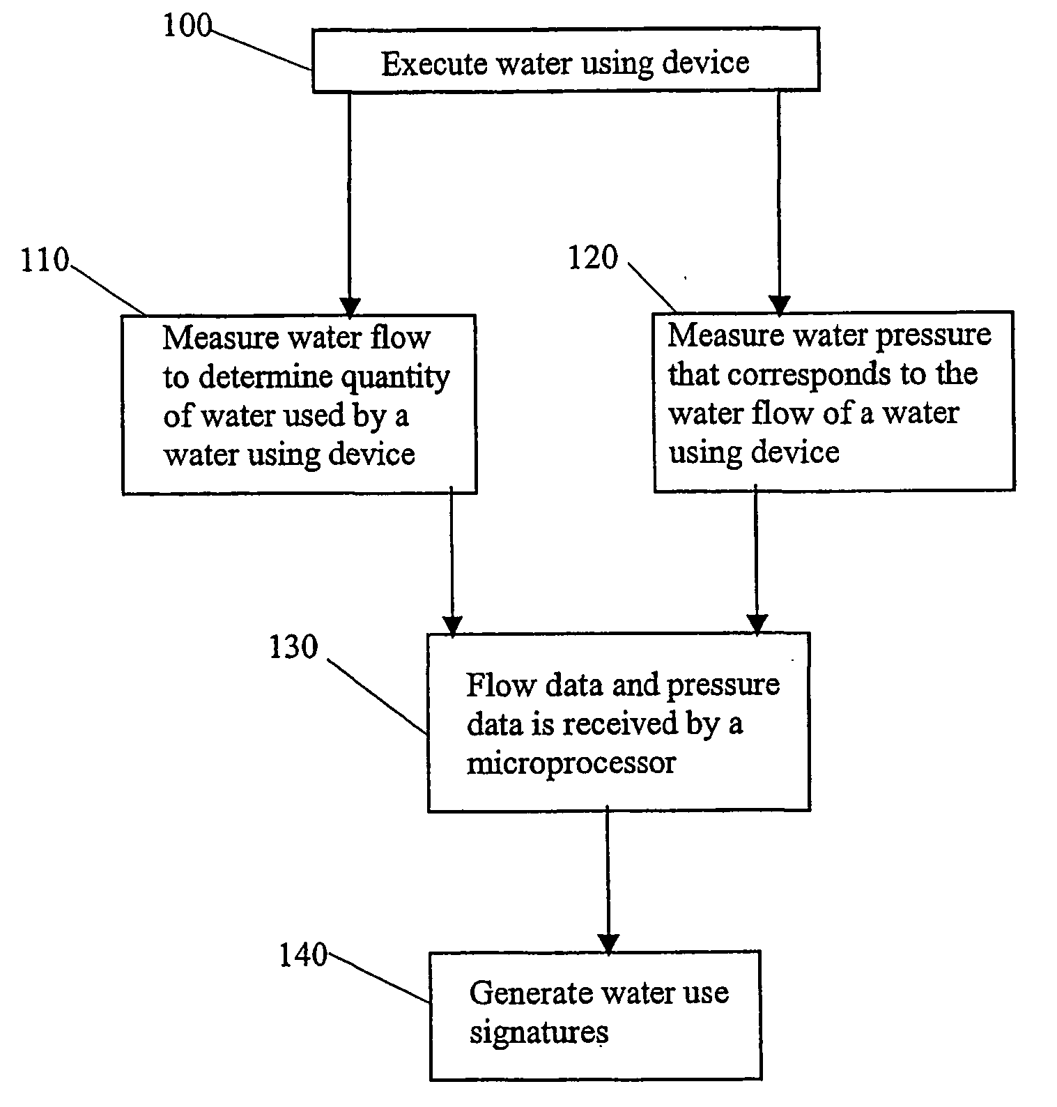
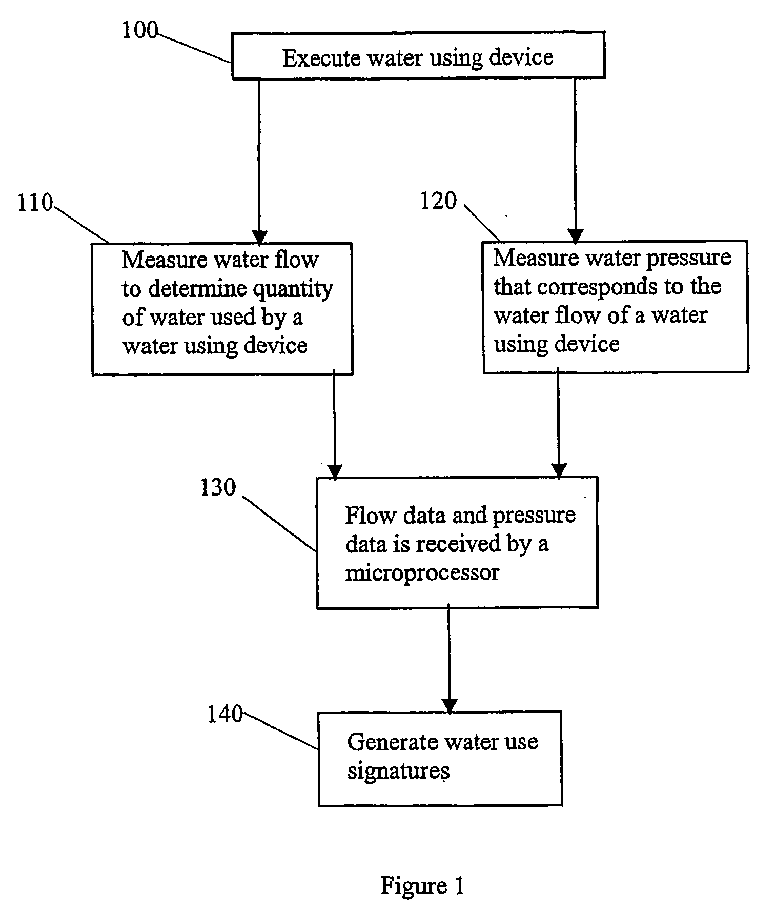
[0022] In FIG. 1 a method for determining a water use signature for a water using device generally comprises the following steps: executing a water using device 100; measuring water flow to determine the quantity of water used by the water using device 110; measuring the corresponding water pressure 120, transmitting flow data and pressure data to a microprocessor 130; and the microprocessor generating baseline data comprising water use signature and corresponding water pressure information 140. The microprocessor is programmed to store the baseline data. The microprocessor will then compare the baseline data with actual water usage signature and corresponding actual water pressure information to identify a flow anomaly.

[0023] In a preferred embodiment the water use signature of the baseline data 140 is obtained from a single water meter that was preferably installed during original construction at the site. The single meter is used to monitor water usage of all devices on the wate...


PUM


Abstract

A method is provided for identifying a flow anomaly in a system having first and second water using devices, comprising: generating baseline data comprising water use signatures and corresponding water pressure information regarding the water using devices; comparing the baseline data with actual water usage signatures and corresponding actual water pressure information to identify a flow anomaly with the water using devices; and providing information on the flow anomaly to an individual. It is especially contemplated that baseline data are generated for multiple devices coupled to a common water supply system, with baseline data from two or more water using devices compared against future water use patterns of the same devices. Apparatus to accomplish these tasks is preferably housed in an irrigation controller, which may be advantageously coupled to a flow meter.

Description

[0001] This application is a Continuation-In-Part of U.S. patent application Ser. No. 10 / 297,146 filed on Aug. 11, 2003.FIELD OF THE INVENTION [0002] The field of the invention is water flow meters. BACKGROUND OF THE INVENTION [0003] In arid areas of the world water is becoming one of the most precious natural resources. Meeting future water needs in these arid areas may require aggressive conservation measures. Each individual living or working in these arid areas should take the initiative to start conserving water. Most individuals are aware of some of the steps they can take to conserve water, such as installing low or ultra low flush toilets, installing water saving shower heads, sweeping rather than hosing off the driveway, checking for leaks in the water system and irrigation system, and irrigating the landscape efficiently. However, with the last two steps, many individuals may not be aware of leaks in their water lines or irrigation systems and / or they are not aware of what...

Claims


Application Information

Patent Timeline
12 Jan 2006
Publication
US20060009928A1
IPC
G01F13/00; E03B7/00; G01M3/28; G06D1/00
CPC
E03B7/071; G01M3/2815; G01M3/2807; G01F15/06; G01F15/063; G01F15/0755; Y02A20/15
Inventors
ADDINK, JOHN W.; ADDINK, SYLVAN