Thermal history sensor

a technology of thermodynamics and sensors, applied in the field of thermodynamic effects on materials, can solve the problems of material components exposed, various periods of time suffer mechanical properties degradation, and component failur

Inactive Publication Date: 2005-12-13
AIR FORCE US SEC THE THE
View PDF14 Cites 46 Cited by
  • Summary
  • Abstract
  • Description
  • Claims
  • Application Information

AI Technical Summary

Benefits of technology

[0013]Another object of the invention is to provide a relatively inexpensive sensor that can be positioned adjacent to a component in order to obtain information about the thermal history of the component.
[0014]Another object of th

Problems solved by technology

Material components exposed to high temperatures (above 400 kelvin) for various periods of time suffer degradation in their mechanical properties.
Such degradation may ultimately lead to failure of the component, especially where such materials are exposed to repeated temperature cycles, extreme temperatures, rapid heating and cooling, or accompanied by other stressors, such as pressure and oxidation.
Many such components are primarily affected by thermal stressors, which contribute to microstructural changes, creep, thermal stresses, thermal fatigue, and thermal shock, as well as oxidation-induced degradation of the material.
Failure of components on aircraft, as a result of thermally induced degradation, can cause catastrophic damage in both economic and human terms.
These solutions, while generally effective, may result in either the premature replacement of a costly component or the failure to replace the component when necessary, resulting in a catastrophic failure.
Such procedures, however, cannot distinguish between different stressors having vastly different effects on the useful lifetime of components.
In addition, the change in resistance is rapid above a threshold temperature for a given mat

Method used


Image

  • Thermal history sensor
  • Thermal history sensor
  • Thermal history sensor

Examples


Embodiment Construction

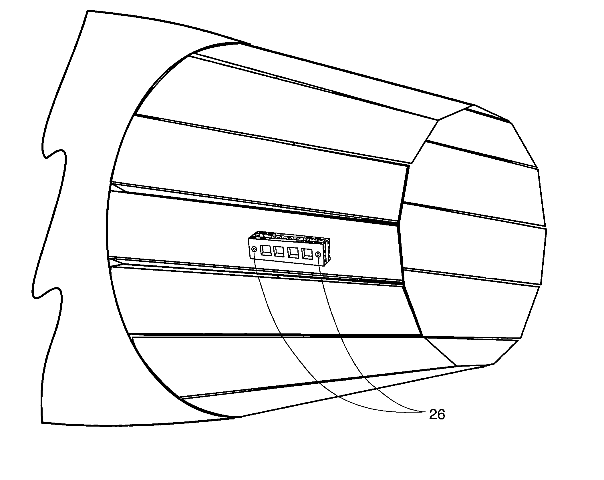
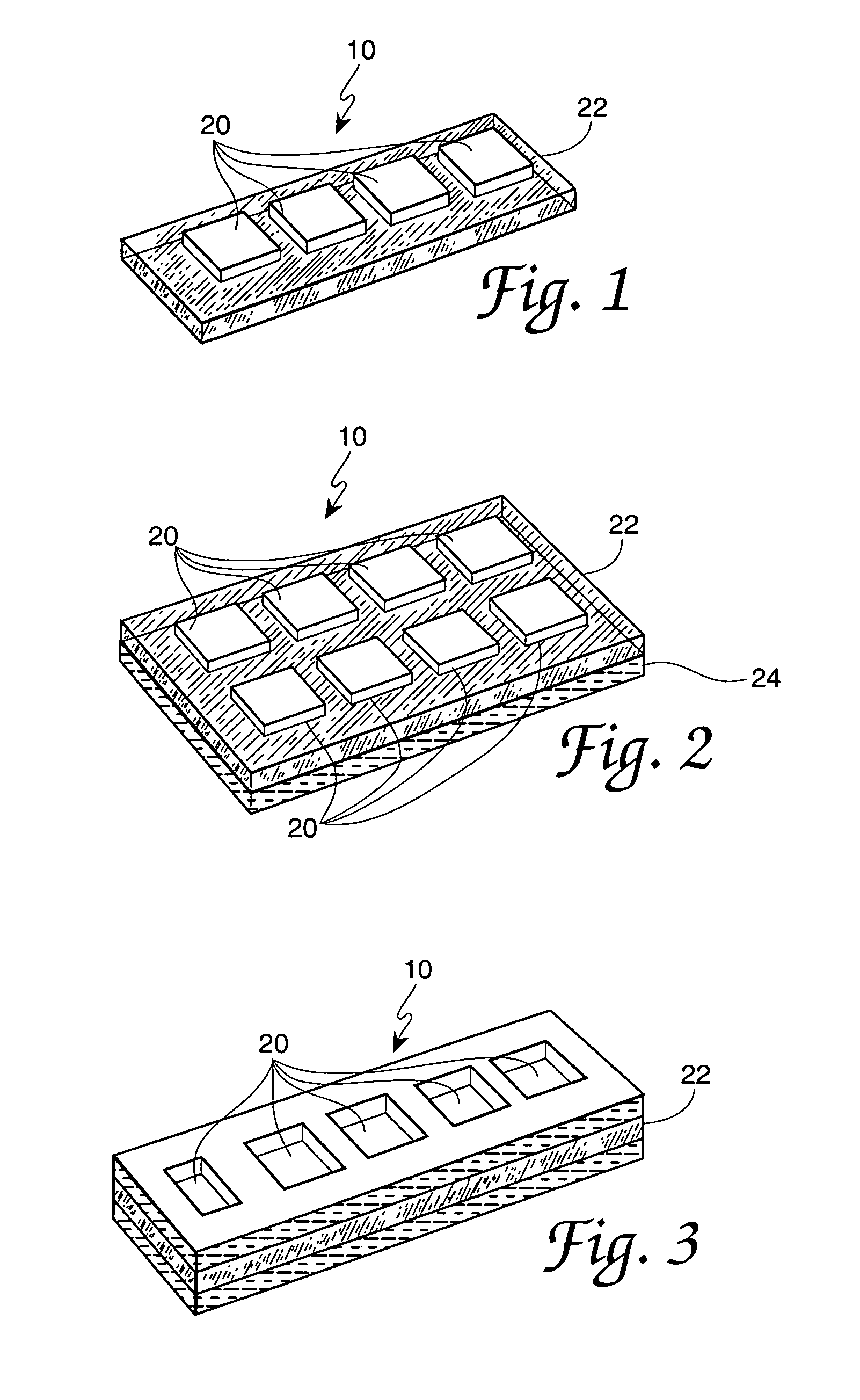
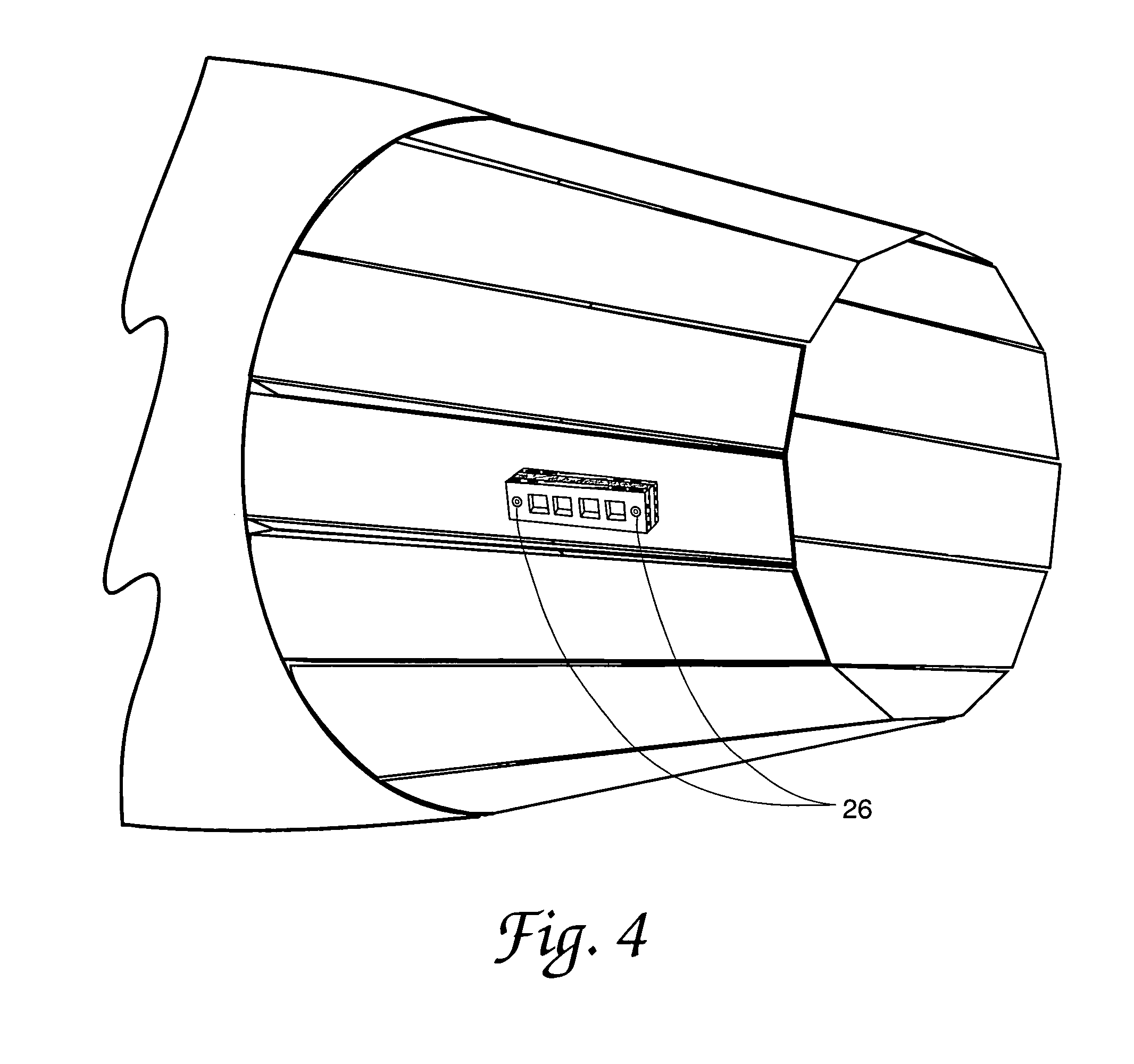
[0027]Referring to the drawings, FIG. 1 depicts one embodiment of the sensor 10 having four different glass ceramic substrates 20 secured to a reflective surface 22. In this particular embodiment, glass ceramic substrates 20 are equally sized and spaced and are positioned linearly (single row array) within the same plane. An alternative embodiment of sensor 10, in which glass ceramic substrates 20 are arranged in a two-dimensional array, is illustrated in FIG. 2. In one embodiment, all glass ceramic substrates 20 have the same dimensions—as well as the same average height and width (i.e., substantially square), though this is not essential. In one embodiment, glass ceramic substrates 20 measure approximately 1 cm square. In other embodiments, glass ceramic substrates 20 are considerably smaller.

[0028]The sensor 10 includes at least two glass ceramic substrates 20 having different compositions. In one embodiment, no two glass ceramic substrates 20 of sensor 10 have the same material ...


PUM

PropertyMeasurementUnit
Temperatureaaaaaaaaaa
Angleaaaaaaaaaa
Compositionaaaaaaaaaa

Abstract

An improved thermal history sensor having multiple glass ceramic substrates with unique compositions is disclosed. By positioning the sensor adjacent to a component subject to thermal stressors, each of the glass ceramic substrates react with a different rate of nucleation and crystal growth and thus yield a specific measure of opacity. By comparing these values representing the opacity for each glass ceramic substrate, or thermal history fingerprint, to baseline data, information about the expected remaining useful lifetime of the component may be obtained.

Description

RIGHTS OF THE GOVERNMENT[0001]The invention described herein may be manufactured and used by or for the Government of the United States for all governmental purposes without the payment of any royalty.BACKGROUND OF THE INVENTION[0002]1. Field of the Invention[0003]The present invention relates to the field of thermal effects on materials, and in particular, the analysis of the thermal history of a material for monitoring the structural integrity of material components exposed to temperature stressors.[0004]2. Description of the Related Art[0005]Material components exposed to high temperatures (above 400 kelvin) for various periods of time suffer degradation in their mechanical properties. Such degradation may ultimately lead to failure of the component, especially where such materials are exposed to repeated temperature cycles, extreme temperatures, rapid heating and cooling, or accompanied by other stressors, such as pressure and oxidation. Material components, such as those on a j...

Claims


Application Information

Patent Timeline
IPC IPC(8): B32B9/04G01K3/00G01K3/04G01K11/12G01N21/71
CPCG01K3/04
Inventor FAIR, GEOFF E.PARTHASARATHY, TRIPLICANE A.KERANS, RONALD J.
Owner AIR FORCE US SEC THE THE
Why Eureka
Try Eureka