Auto-adjusting sound masking system and method

a masking system and auto-adjusting technology, applied in the direction of sound producing devices, transducer circuits, speech analysis, etc., can solve the problem of laborious trial and error methods

Active Publication Date: 2006-01-12
SOFT DB
View PDF34 Cites 31 Cited by
  • Summary
  • Abstract
  • Description
  • Claims
  • Application Information

AI Technical Summary

Problems solved by technology

A main challenge remains in adjusting this ideal spectrum to any target environment, taking into account a number of parameters including a size of the room, a coating of the walls of th

Method used


Image

  • Auto-adjusting sound masking system and method
  • Auto-adjusting sound masking system and method
  • Auto-adjusting sound masking system and method

Examples


Embodiment Construction

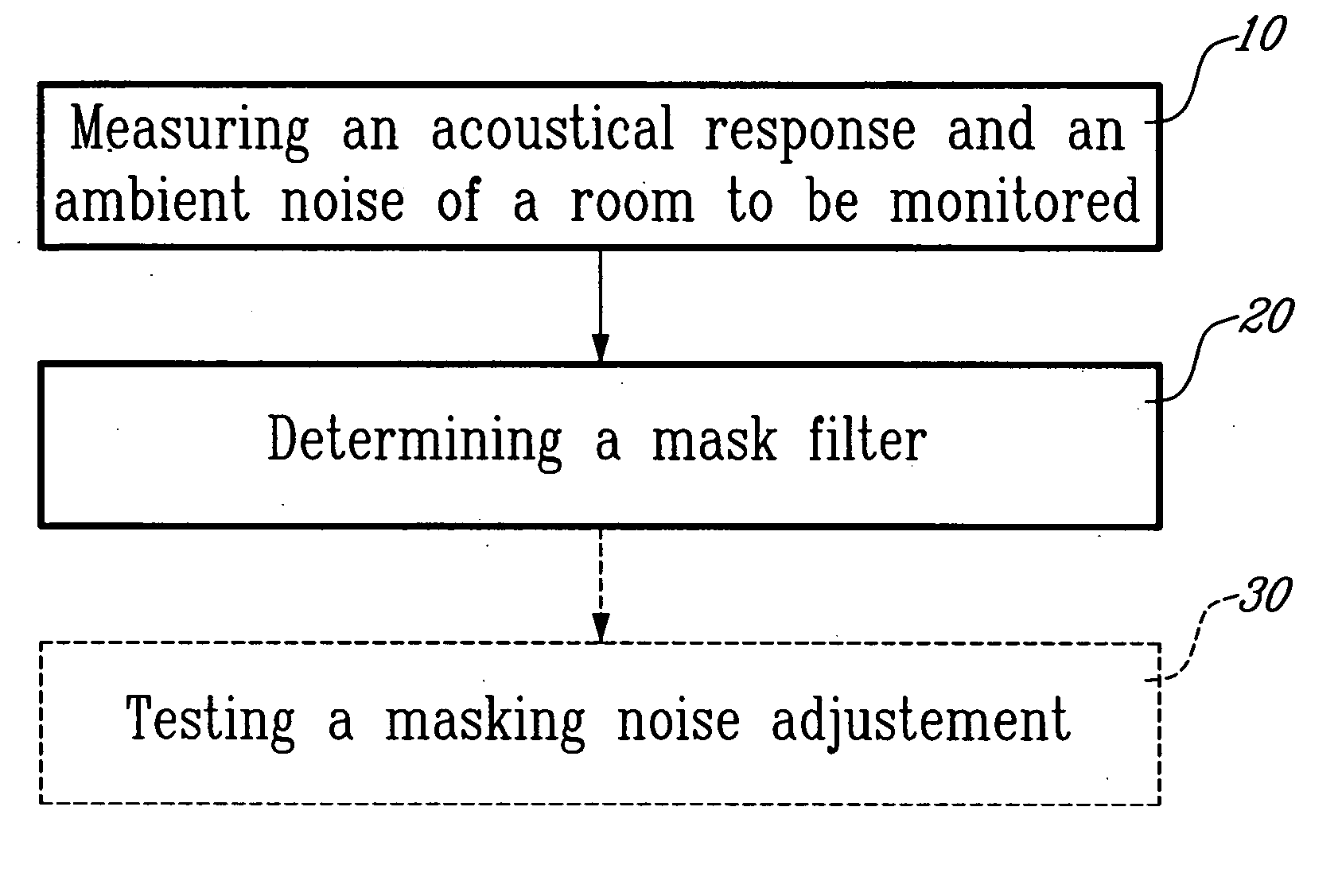
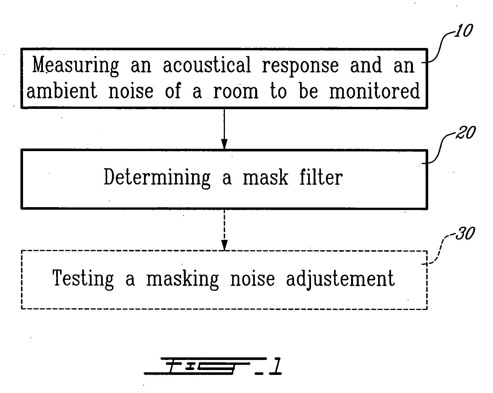
[0021] As illustrated in FIG. 1 of the appended drawings, a method according to a first aspect the present invention generally comprises measuring an acoustical response and an ambient noise of a room to be monitored (step 10); and

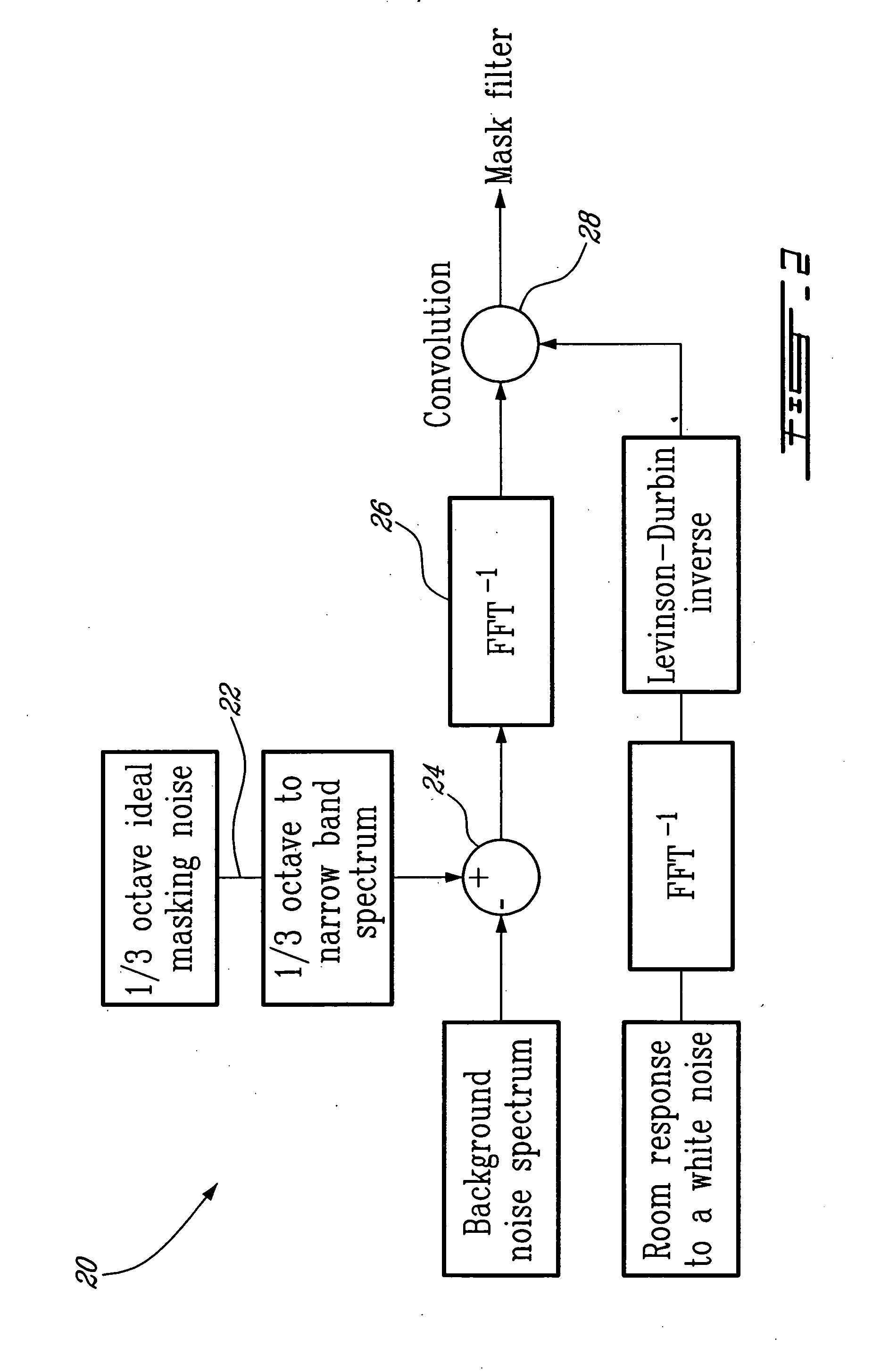
[0022] determining a mask filter (step 20). A step of testing auto-adjustment of a masking noise generated through the mask filter determined in step 20 may be further contemplated (step 30).

[0023] In step 10, the acoustical response and the ambient noise of the room to be monitored are measured so as to determine the acoustical characteristics of the room in an emission frequency band of a target masking noise.

[0024] In step 20, a correction filter (line 42FIG. 3) to be applied to the measured acoustical response (line 40FIG. 3) of the room in order to yield a flat frequency response (line 44FIG. 3) in an emission frequency band of the target masking noise is determined, thereby allowing overcoming this acoustical response of the room.

[0025] More prec...


PUM


Abstract

A system and method for generating a masking noise level and spectrum automatically adjusted to obtain a target masking noise spectrum in a room. The system comprises a white noise generator and a mask filter automatically determined according to a correction of an acoustical response of the room and to the target masking noise corrected by an ambient noise.

Description

FIELD OF THE INVENTION [0001] The present invention relates to sound masking systems and methods. More specifically, the present invention is concerned with an auto-adjusting sound masking system and method. BACKGROUND OF THE INVENTION [0002] Sound masking systems basically include a masking sound generator, an equalizer, a power amplifier and one or more loudspeakers. [0003] As sound masking systems are being developed, it is now known that efficiency thereof is linked to their ability to emit an ideal masking noise spectrum with an adequate precision. The ideal masking noise is defined as achieving optimized speech privacy at a listener's position for example (Acoustical Design of Conventional Open Plan Offices, 2003). [0004] A main challenge remains in adjusting this ideal spectrum to any target environment, taking into account a number of parameters including a size of the room, a coating of the walls of the room, the furniture of the room and the ambient noise for example. The ...

Claims


Application Information

Patent Timeline
IPC IPC(8): G10L21/02G10K11/175
CPCG10K11/175G10K11/1752H04K3/42H04K3/45H04K3/825H04K3/94H04K2203/12
Inventor L'ESPERANCE, ANDREBOUDREAU, ALEX
Owner SOFT DB
Why Eureka
Try Eureka