Retaining wall with plastic coated wooden panels

a technology of retaining walls and wooden panels, applied in the direction of walls, construction, building components, etc., can solve the problems of rot and deterioration, wooden panels are subject to deterioration, and the process of deterioration is not easy to achiev

Inactive Publication Date: 2006-01-19
CMI CO LTD
View PDF12 Cites 8 Cited by
  • Summary
  • Abstract
  • Description
  • Claims
  • Application Information

AI Technical Summary

Problems solved by technology

However, wooden panels are subject to deterioration from marine borers and other insects, and rot and deterioration from impact by other objects.
This slows the deterioration process of the panels from marine borers but provides the potential hazard of leaching of hazardous chemicals from the panels into the water and adjacent surroundings, possibly causing an environmental hazard.
Also, wooden panels tend to shrink and / or swell in response to their environmental conditions.
This tends to cause gaps between the panels in the wall structure, allowing water, silt and other undesirable elements to pass with water through the wall structure.
However, the shaped panels are sometimes considered undesirable because they do not present a flat surface that is more visually and structurally pleasing.
The panels formed of plastic have good compression strength properties so that they can be driven into the earth, but their lateral strength properties are weaker than the metal panels.
While the metal and plastic panels have been successful in avoiding deterioration by marine borers and other insects, the profiles of the panels are still objected to by many since they do not provide a pleasing, less industrial look like the flat panels.
However, the known panels made of wooden boards with plastic exteriors have not been successful in forming panels that are connected edge-to-edge to form a strong and continuous barrier that retards the movement of water and water-borne particles through the wall structure.
The retention of water between the boards and their tongues at one edge of the panels and / or between the boards and their grooves at the other edge of the panels introduces the hazard of freezing of the retained water in the panels in cold weather and deterioration of the adjacent surfaces of the plastic and the wood of the panels.

Method used


Image

  • Retaining wall with plastic coated wooden panels
  • Retaining wall with plastic coated wooden panels
  • Retaining wall with plastic coated wooden panels

Examples


Embodiment Construction

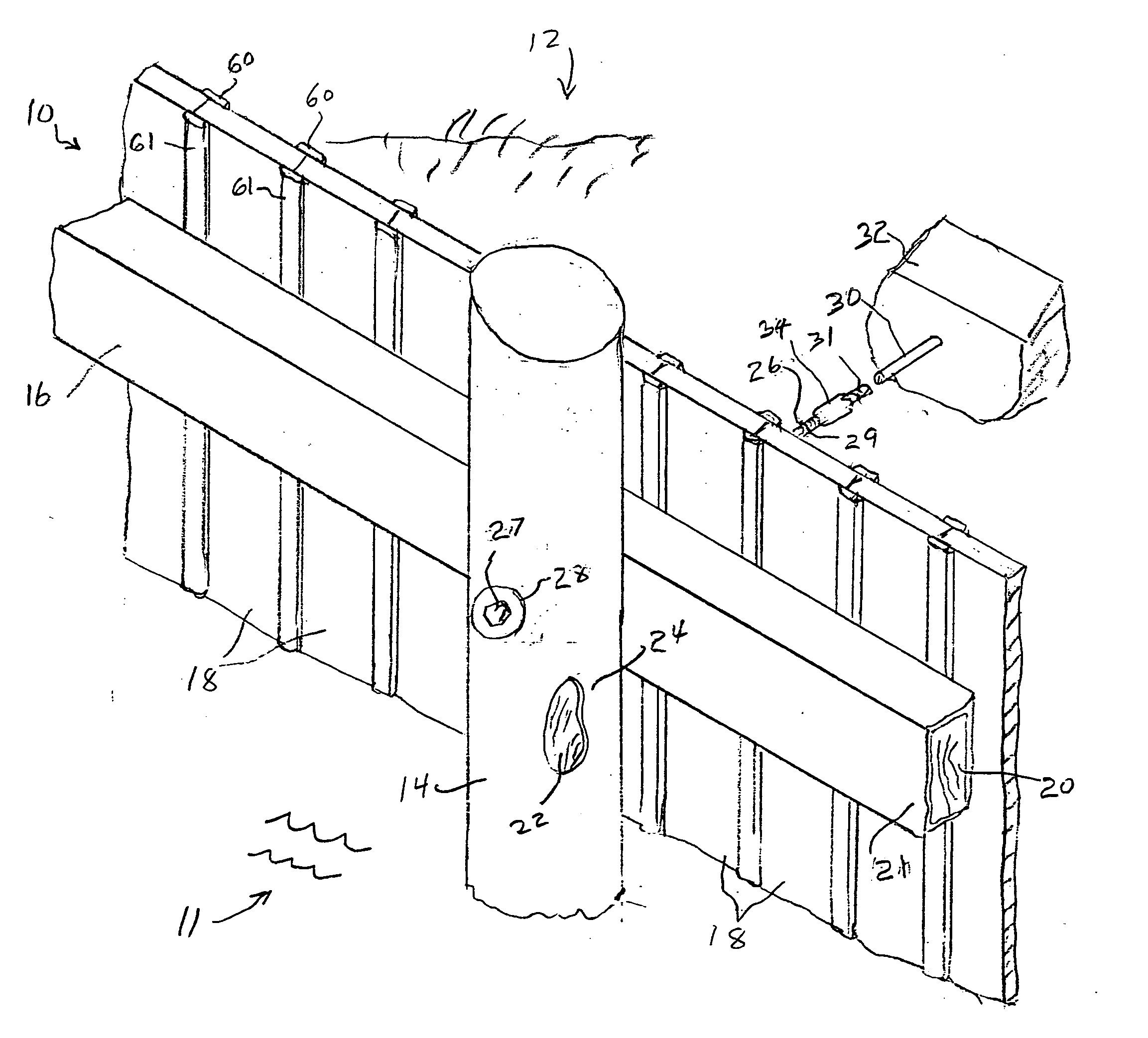
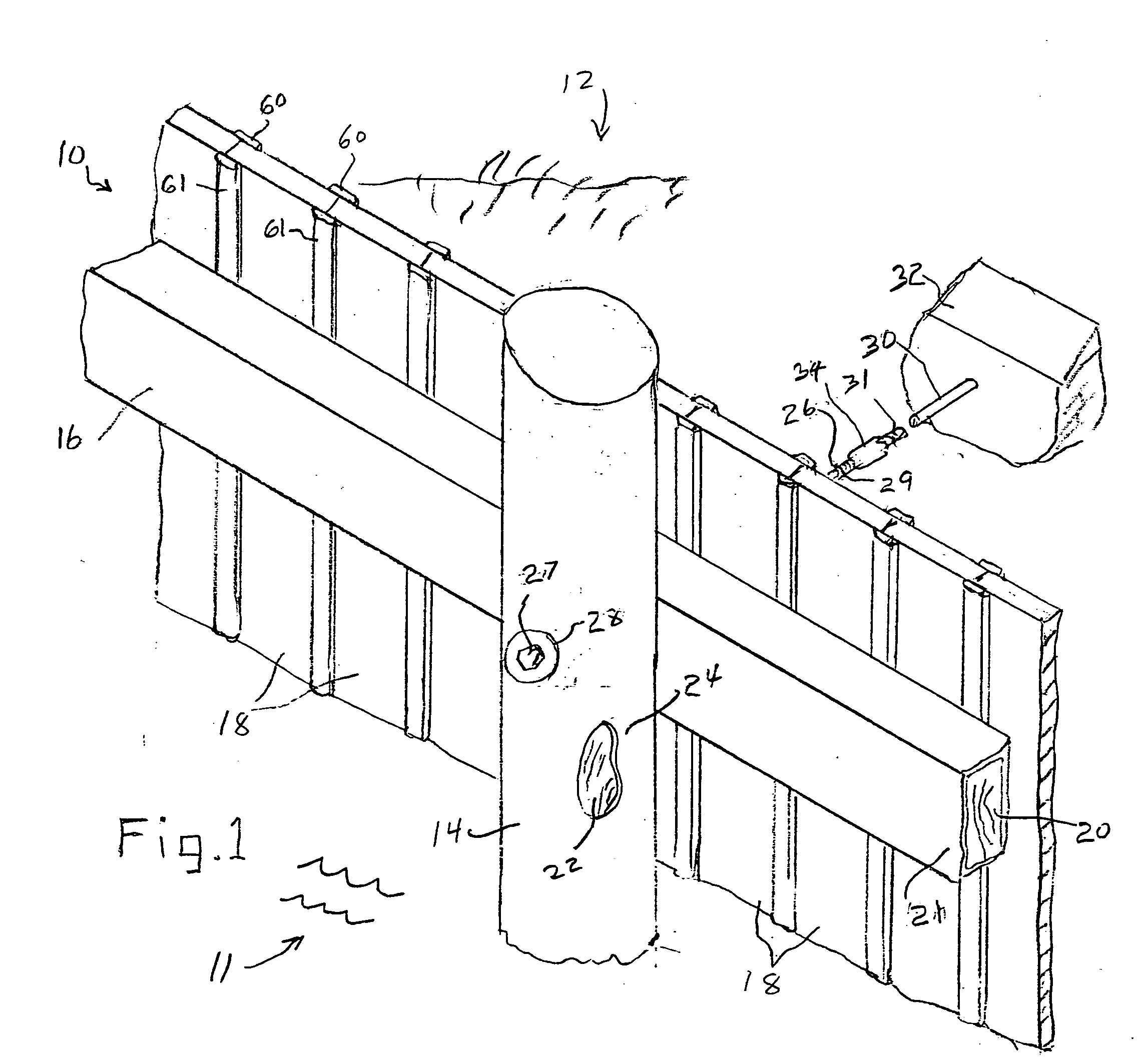
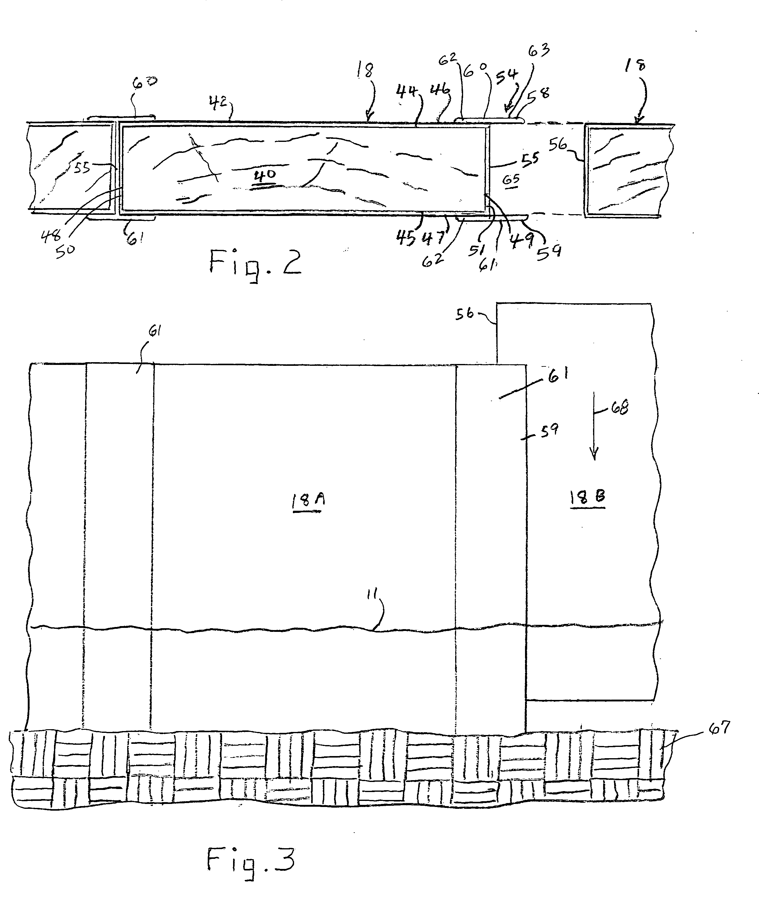
[0021] Referring now in more detail to the drawings, in which like numerals indicate like parts throughout the several views, FIG. 1 illustrates a retaining wall 10 that has been assembled for placement between a body of water 11 and a land mass 12, for separating the water from the land. While only a portion of the retaining wall is illustrated, it will be seen that it includes a plurality of vertical piles 14, horizontally extending wales 16, and a plurality of elongated, vertically oriented structural panels 18 placed in edge-to-edge relationship. The piles 14 are oriented vertically so that they can be driven downwardly through the water 11 and into the earth below so that the lower end portions of the piles are embedded in the earth and remain stabilized by the earth. Wales 16 are arranged in end-to-end relationship and extend horizontally between the piles 14 and the land mass 12. The structural panels are elongated and extend vertically. The structural panels are driven downw...


PUM


Abstract

A retaining wall (10) is formed by a series of structural panels (18) arranged in edge-to-edge relationship, supported by horizontally extending wales (16) and vertically extending piles (14). The panels are formed of a rectangular board (40) with a plastic envelope (42) adhered to the board. Strips (60 and 61) are adhered to the plastic material at one edge portion of each panel, with the strips forming protruding lips (58 and 50) that receive the second edge of an adjacent panel, thereby guiding the new panels into place and forming a barrier to the movement of water and water borne debris between the panels.

Description

CROSS REFERENCE [0001] This application is a continuation-in-part of co-pending U.S. patent application Ser. No. 10 / 891,930, filed Jul. 15, 2004 in the U.S. Patent and Trademark Office.FIELD OF THE INVENTION [0002] This invention concerns retaining walls of the type used for retaining the earth at the water's edge of a body of water, particularly where the wall is to be exposed to harsh environmental conditions, such as extreme heat and cold, moisture, insects, abrasion, etc. BACKGROUND OF THE INVENTION [0003] Barrier walls can be formed of a plurality of elongated vertically oriented piles having their lower extremities driven into the earth to a depth sufficient to support the piles and their associated structural elements. Horizontally extending wales are mounted to the piles, and vertically oriented structural panels are partially driven into the earth adjacent the wales. Usually, the panels have interlocking male and female opposed edges that are used to connect to the edges of...

Claims


Application Information

Patent Timeline
Patent Type & Authority Applications(United States)
IPC IPC(8): E04B2/00
CPCE02D29/0266
Inventor IRVINE, JOHN E.HARGRAVE, STEVE E.
Owner CMI CO LTD
Why Eureka
Try Eureka