
Electrical wiring for buildings

a technology for electrical wiring and buildings, applied in the direction of insulated cables, cable junctions, capacitors, etc., can solve the problems of affecting the quality of electrical wiring, and affecting the safety of electrical wiring, etc., and achieves the effects of low cost, high quality control in the factory environment, and very economical manufacturing

Active Publication Date: 2006-01-19
WBC IP PTY
View PDF6 Cites 81 Cited by
  • Summary
  • Abstract
  • Description
  • Claims
  • Application Information

AI Technical Summary

Benefits of technology

[0022] It is anticipated that a loom and respective connectors with blanks and outlets sockets can be manufactured very economically in a factory so that the cost associated with such manufacture can be small. Further, the control of quality in a factory environment can also be considered to be higher than might be the case where installation is individually customised for each building.
[0023] It is envisaged that such manufacture can also be accomplished in locations where costs associated with such manufacture can be kept very low.
[0024] Accordingly, the high-cost of an electrician having to individually locate and bare and connect cables within a building during the installation process can be reduced insofar that the time necessary for a lot of the baring of wires, connections and other main tasks associated with the traditional method can now either be reduced or removed.
[0029] The significant advantage expected from this arrangement is that the wiring itself will have been terminated in factory conditions where quality control can be of the highest level and it can be in each case pre-inspected and even tested prior to sale or installation in the building.

Problems solved by technology

Any one of these joins can be a source of serious difficulty.
If any one of these joins is loose or works loose overtime and the bare wire stays close but is separated but within an arcing distance from adjacent conductors or the terminal block there becomes the high risk of arcing which will result in heating which in turn then can lead to adjacent vulnerable items starting to burn and of course the possible destruction by fire of the building.
Such wiring and joins are usually deliberately in places out of sight which means that if there is a problem it may not be readily observable and this then clearly leads to a potential serious danger.
A further difficulty is that, because any wiring by its current nature needing to be a customised process, does need specifically trained workman to accomplish the task.
It is also implicitly a slow process because it is very much a manual process where a skilled worker (an electrician) estimates a size and quantity of cable to be used for each run in a building, prepares such cable, and then has to have a sufficient available stock of fittings, junctions, switches, and cables of various capacities on hand to complete a wiring job.
However the bore being formed of an opaque material (brass) does not allow the location of the end of the wire to be actually seen and a usual process for an electrician is that a wire is inserted and the electrician can feel that it has gone in enough to be sure that it will have a sufficient length in the bore for the screw to effectively engage and hold this.
If the feel test is deceived then there can be a dangerous situation with partial contact or worse where the wire or wires is or are loose and over time will intermittently contact with a possible result of arcing etc.
The problems then can be seen which are that current systems do have difficulties and also incur costs that may be considered substantial.

Method used


Image

  • Electrical wiring for buildings
  • Electrical wiring for buildings
  • Electrical wiring for buildings

Examples


Embodiment Construction

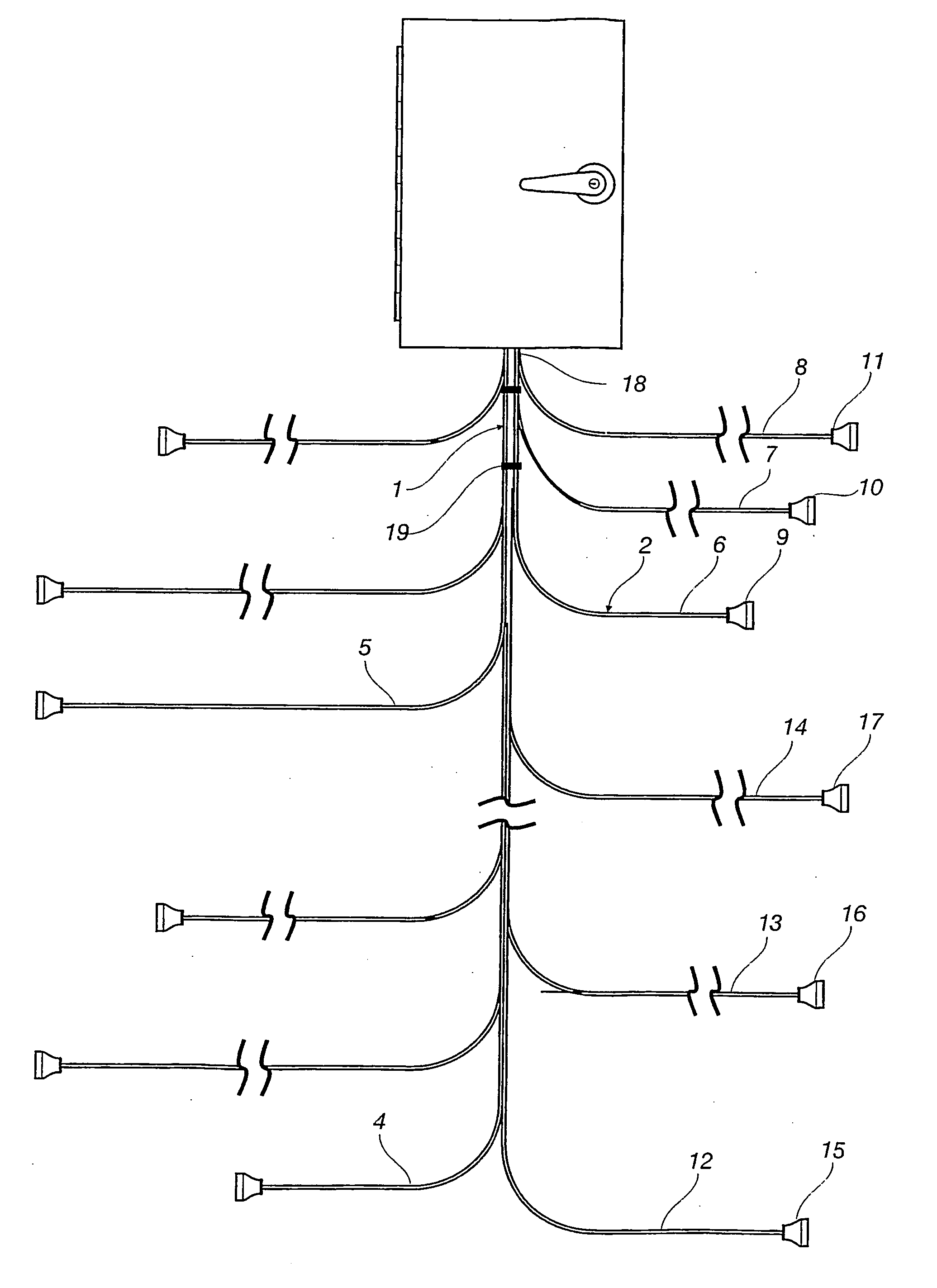
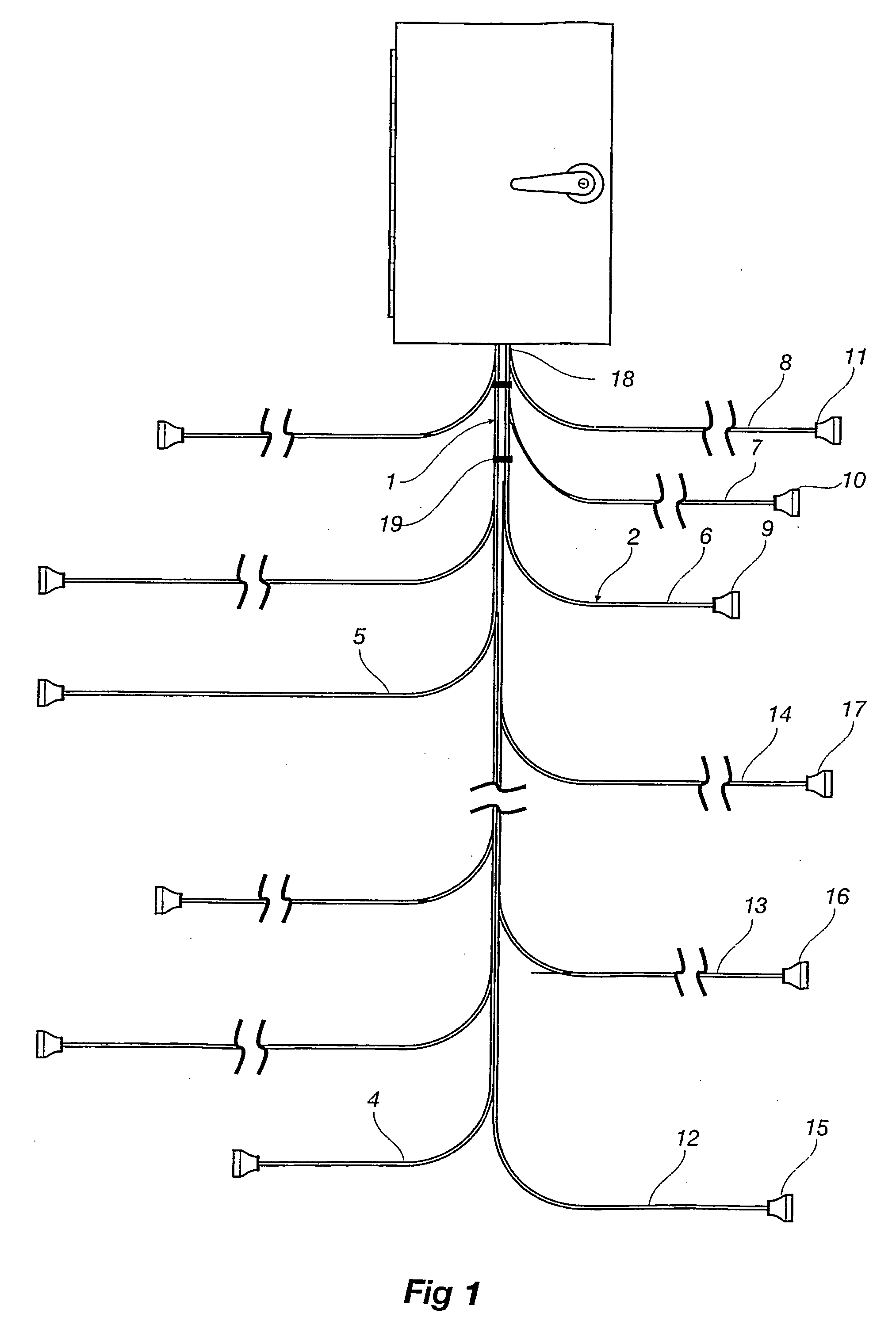
[0040] Now referring to the drawings the assembly 1 is manufactured as a loom which includes in this case four separate cables 2, 3, 4, 5, each of which have three cores each which are each electrically insulated one from the other and which are held together so as to be kept in an adjacent alignment, and each of which are separately coloured in a traditional way in which earth, active and neutral cores are traditionally coloured with conventional mains electrical power wiring.

[0041] Each of these four cables are arranged in turn give rise to a plurality of branches stemming there from, each branch terminating at a female socket which is to say where the electrical connectors are embedded with the socket and it is there fore adapted to receive a male plug which has pins intended to enter into the female socket which are otherwise inaccessible and makes electrical connection thereby.

[0042] In this case cable 2 has branches 6, 7, 8 terminating at sockets 9, 10, 11 respectively. Simi...


PUM


Abstract

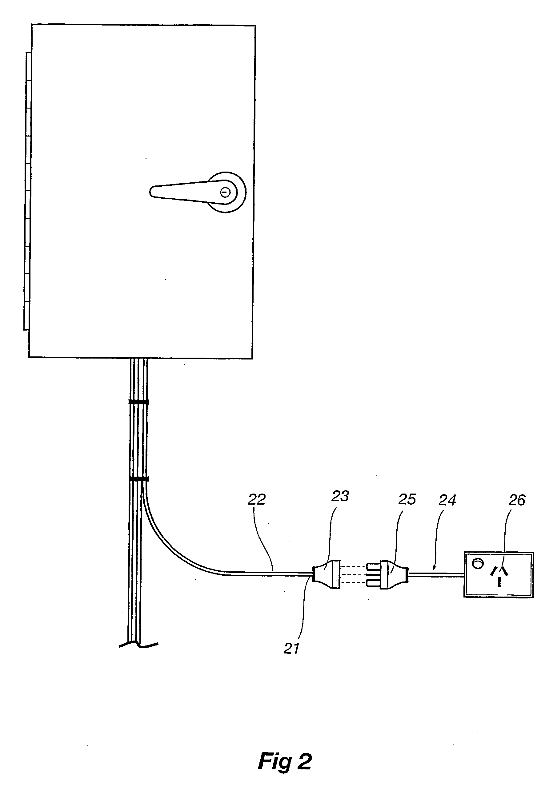
A method of wiring a building and a building so wired where there is a pre-made loom (1) which has a plurality of spaced apart sockets (15, 16, 17) at regular intervals along a length of the loom (1) and which is strung through the building placing thereby conveniently positioned female sockets (15, 16, 17) at regular locations along the length of the loom (1) and where outlets are then connected at a most conveniently any one of the sockets (15, 16, 17) by having for each a male plug (25) to be connected thereto where the male plug (25) itself connected electrically to a unit such as a mounted switched outlet, or electrical appliance or the like.

Description

[0001] This invention relates to electrical wiring for buildings and in particular relates to a method of electrical wiring of a building for mains electrical power supply, to looms for assistance in wiring, and to a building with and installation incorporating electrical wiring. BACKGROUND OF THE INVENTION [0002] To currently wire buildings for a supply of electrical mains power through the building it is common on a customized basis to have insulated cables strung through the building by a specialist electrician where each length of wire and each termination is uniquely and separately prepared and made by for instance baring at respective ends some of the insulation from a wire, inserting the thus bared raw end into a terminal junction, then tightening a screw so as to keep the wire in position. [0003] Such a process is repeated for each length of wire and for each core for instance the active wire, the neutral wire and where appropriate the earth connection each at both ends of e...

Claims


Application Information

Patent Timeline
IPC IPC(8): H02G3/04H02B1/20H02G1/14H02G3/00H02G3/02H02G15/08
CPCH02G3/288H02G3/00
Inventor FAHEY, MARKT
Owner WBC IP PTY
Learn More