Variable energy attenuating apparatus

a technology of energy attenuating apparatus and variable energy, which is applied in the direction of shock absorbers, elastic dampers, pedestrian/occupant safety arrangements, etc., can solve the problems of dangerously high load and very little seat stroking, light or heavy occupants may not receive sufficient protection, and heavy seat occupants may experience very light load and very long seat stroking

Inactive Publication Date: 2006-01-19
EAST WEST IND
View PDF23 Cites 23 Cited by
  • Summary
  • Abstract
  • Description
  • Claims
  • Application Information

AI Technical Summary

Benefits of technology

[0005] The present invention provides an energy attenuating apparatus for a seat that has a varying resistance to deformation over its stroke to enable the energy attenuating apparatus to provide adequate protection to seat occupants over a wide range of weights.
[0007] The energy attenuating apparatus may include a housing having first and second portions capable of telescopic movement with respect to each other. The attenuator may be disposed in the housing with first and second ends of the attenuator secured to the first portion, and the bending mechanism may be disposed inside the housing and secured to the second portion. The housing enables the energy attenuating apparatus to be easily installed on a seat or other structure with respect to which the apparatus is to perform energy attenuation.
[0011] The resistance to bending of the attenuator can be varied along its length in a variety of manners, such as by varying the transverse cross-sectional area or the material properties of the attenuator. The resistance to bending can be selected so that the energy attenuating apparatus exerts predetermined forces within a permissible range to a wide range of the population during a crash while maintaining the stroking distance of a seat at a level so that bottoming out does not occur. For example, the attenuator can be selected to provide adequate protection during a crash to seat occupants ranging in weight from the 3rd percentile of females to the 98th percentile of males, with the maximum stroking distance remaining below about 14 inches.

Problems solved by technology

While a seat occupant with a weight near the 50th weight percentile can be adequately protected, a light or heavy occupant may not receive sufficient protection.
A light seat occupant may suffer dangerously high loads and very little seat stroking, while a heavy seat occupant may experience very light loads and very long seat stroking.
Therefore, a seat with a heavy occupant may bottom out before all the energy is attenuated, resulting in very high loads and energy being transmitted to the seat occupant rather than being dissipated by the energy attenuating apparatus.

Method used


Image

  • Variable energy attenuating apparatus
  • Variable energy attenuating apparatus
  • Variable energy attenuating apparatus

Examples


Embodiment Construction

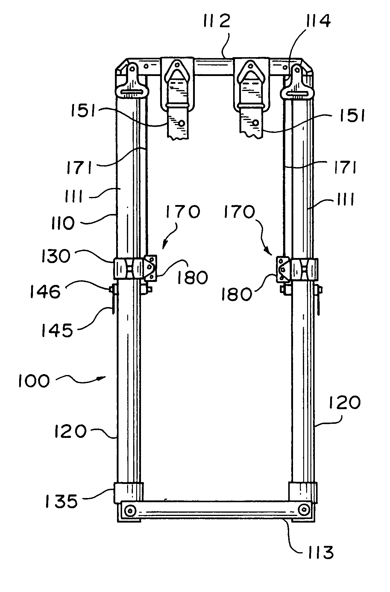
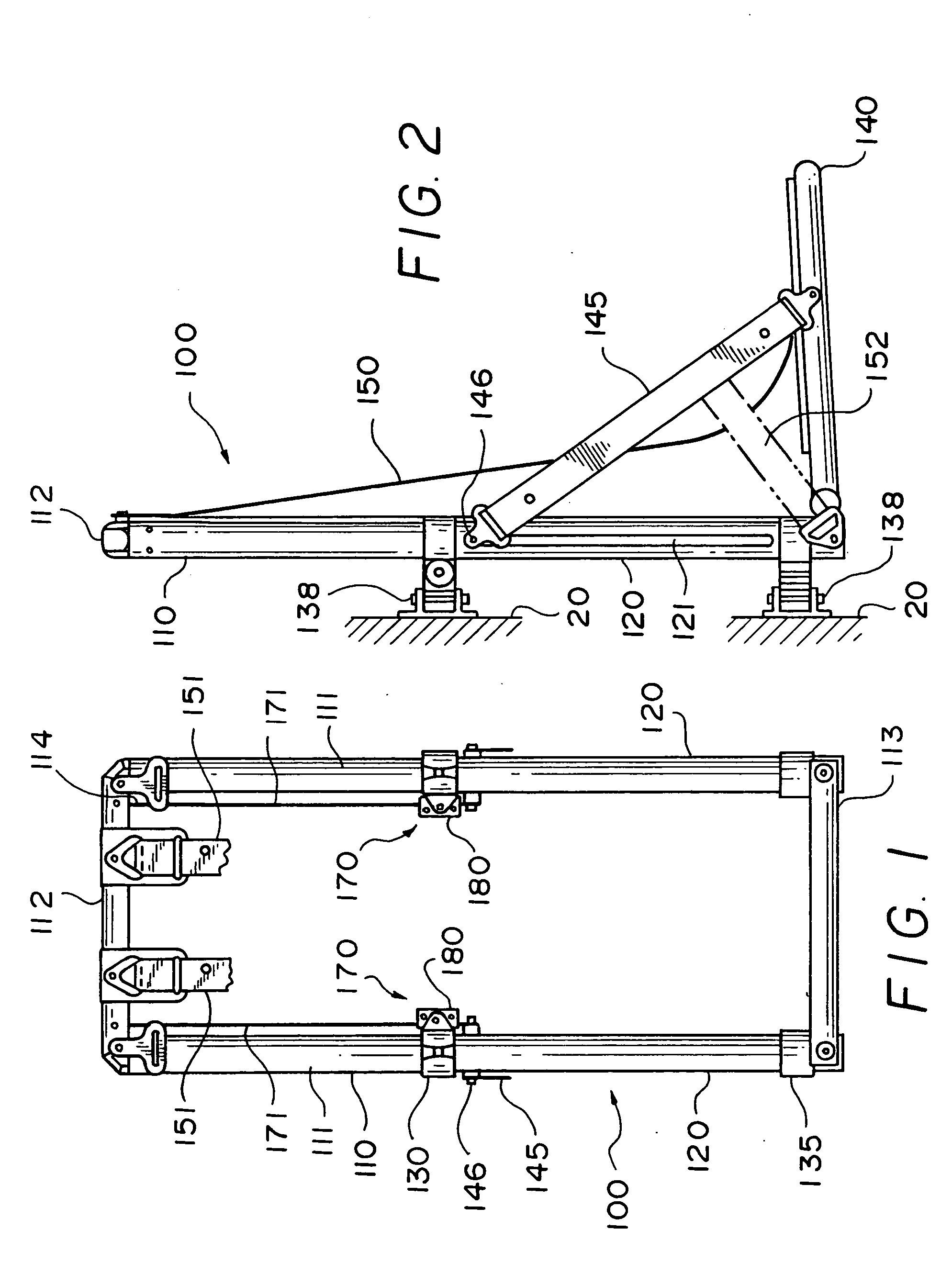
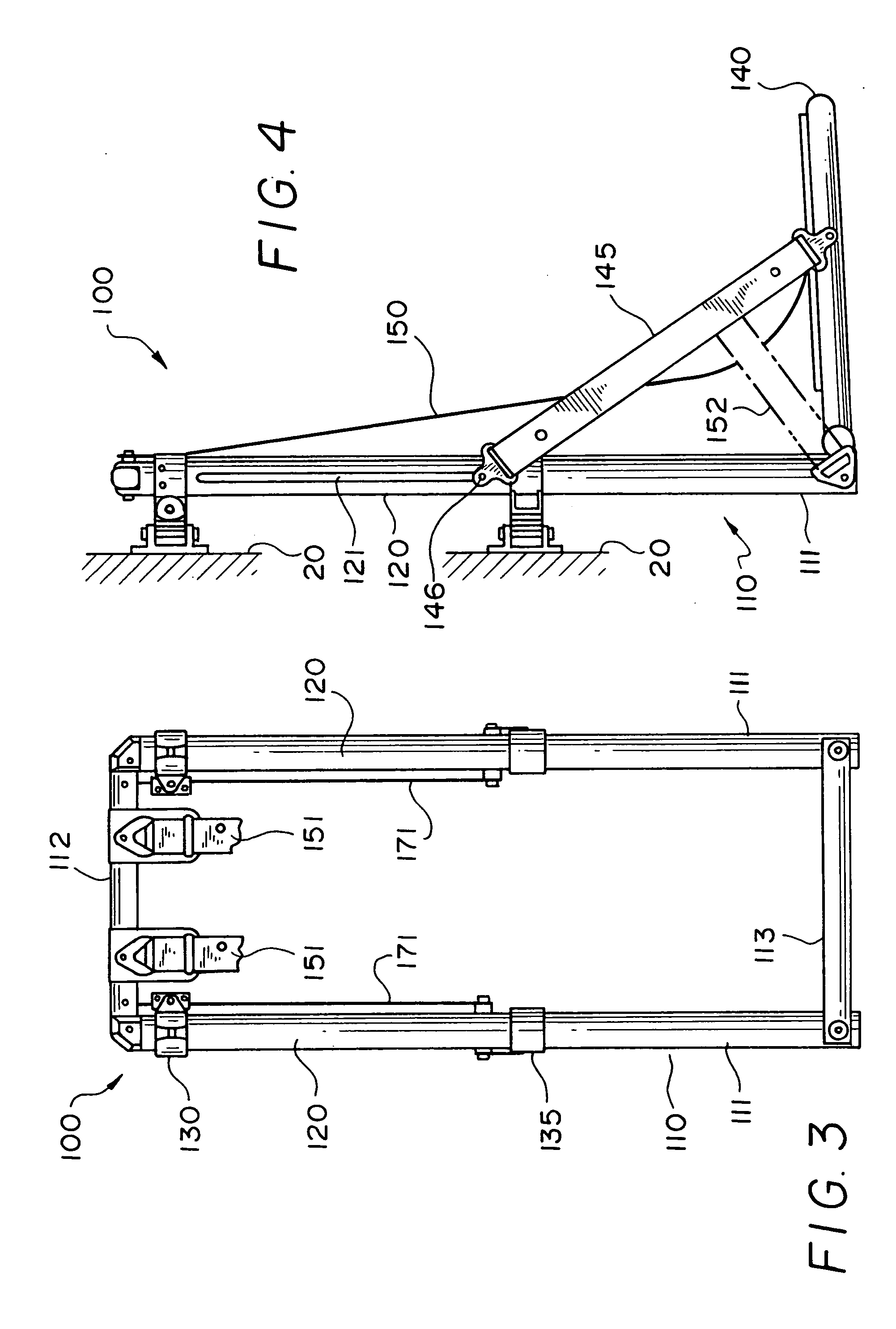
[0023]FIGS. 1-4 illustrate an aircraft seat 100 equipped with an embodiment of an energy attenuating apparatus 170 according to the present invention. The illustrated seat is a troop seat for use in a helicopter, but the seat may be used in other types of aircraft or conveyances, and it is not restricted to use with a particular type of seat occupant. For example, the seat may be for a crew member of an aircraft. The seat 100 may have any structure that enables it to support a seat occupant in a desired manner. The illustrated seat 100 is intended for mounting on a bulkhead 20 or side wall of a helicopter, but alternatively, it may be mounted on a frame connected to the floor or the ceiling of the helicopter. The seat 100 includes a seat back 110 comprising a generally rectangular frame and a seat bottom 140 rotatably mounted on the lower end of the seat back 110 for supporting the buttocks of a seat occupant. The seat back 110 includes a pair of parallel legs 111 and top and bottom...


PUM


Abstract

An energy attenuating apparatus for use with a seat includes an elongated attenuator having a resistance to bending which varies along its length. A bending mechanism defining a nonlinear path receives the attenuator. Translation of the bending mechanism relative to the attenuator in a lengthwise direction of the attenuator produces bending of the attenuator to absorb energy applied to the energy attenuating apparatus.

Description

[0001] This Application is a continuation of application Ser. No. 10 / 105,372, filed Mar. 22, 2002, now pending, which is a continuation of PCT application Ser. No. PCT / U.S.01 / 29912, filed Sep. 25, 2001, now abandon, and a continuation-in-part of Ser. No. 09 / 668,156, filed Sep. 25, 2000 now U.S. Pat. No. 6,378,939 B1.TECHNICAL FIELD [0002] This invention relates to an energy attenuating apparatus for use with a seat that can absorb energy applied to the seat and a seat occupant during a sudden deceleration such as may occur during a crash of an aircraft. It also relates to a seat equipped with such an energy attenuating apparatus. BACKGROUND ART [0003] Seats of aircraft, and particularly military aircraft, are frequently equipped with devices generally referred to as energy attenuating apparatuses for absorbing energy generated during a crash or other sudden deceleration so as to reduce the forces applied to a seat occupant and thereby protect the seat occupant against injury. A numb...

Claims


Application Information

Patent Timeline
Patent Type & Authority Applications(United States)
IPC IPC(8): B64D11/06B60N2/42B60N2/427B64D25/04F16F7/12
CPCB60N2/4242B60N2/42709B60N2/42736B64D11/0619B64D11/0689B64D25/04F16F7/123B64D11/06B64D11/0698B64D11/0691
Inventor KNOLL, FRANK H.GAITO, JOSEPH M.
Owner EAST WEST IND
Why Eureka
Try Eureka