
Airbag device

a technology of airbags and cuffs, which is applied in the direction of pedestrian/occupant safety arrangements, vehicular safety arrangements, vehicle components, etc., can solve the problems of difficult grasping of the internal butt portion from the outside, the inability to break the breakable portion smoothly upon airbag deployment, etc., and achieve the effect of preventing the surrounding from being caugh

Active Publication Date: 2006-01-19
TOYODA GOSEI CO LTD
View PDF3 Cites 42 Cited by
  • Summary
  • Abstract
  • Description
  • Claims
  • Application Information

AI Technical Summary

Benefits of technology

The present invention provides an airbag device that can break the breakable portion of the airbag wrapping member stably upon airbag inflation. The airbag device includes a folded-up body and a wrapping member made of flexible sheet-shaped material. The wrapping member is breakable upon airbag inflation and includes a cover portion and fixing portions. The breakable portion is formed by a cover portion that holds the folded-up body's top face and includes a breakable portion in a region above the base line. The breakable portion is made up of a cover portion with a breakable portion in a plane of the invention, and fixing portions located in extensions from the cover portion perpendicular to the base line. The breakable portion includes a plurality of apertures that connect to each other to form a larger opening upon breakage. The airbag device also includes cut-out portions in edges of the cover portion to confirm the position of the butt portion of the folded-up body and keep the folded-up body in shape. The breakable portion is smoothly broken, and the position of the butt portion does not affect the breakage performance. The airbag device is stable and reliable.

Problems solved by technology

In a conventional airbag device, however, when the wrapping cloth is mounted around the folded-up body in a condition that a butt portion of the ends of the airbag, which is to be disposed proximate to the base line, is deviated from the breakable portion of the wrapping cloth, the breakable portion is not likely to be broken smoothly upon airbag deployment.
In this case, the position of the internal butt portion is not easy to grasp from the outside.
Accordingly, there is a challenge in improving accuracy in making the position of the internal butt portion of the folded-up body generally consistent with the position of the breakable portion.

Method used


Image

  • Airbag device
  • Airbag device
  • Airbag device

Examples


Embodiment Construction

[0033] Preferred embodiments of the present invention are now described below with reference to the accompanying drawings. However, the invention is not limited to the embodiments disclosed herein. All modifications within the appended claims and equivalents relative thereto are intended to be encompassed in the scope of the claims.

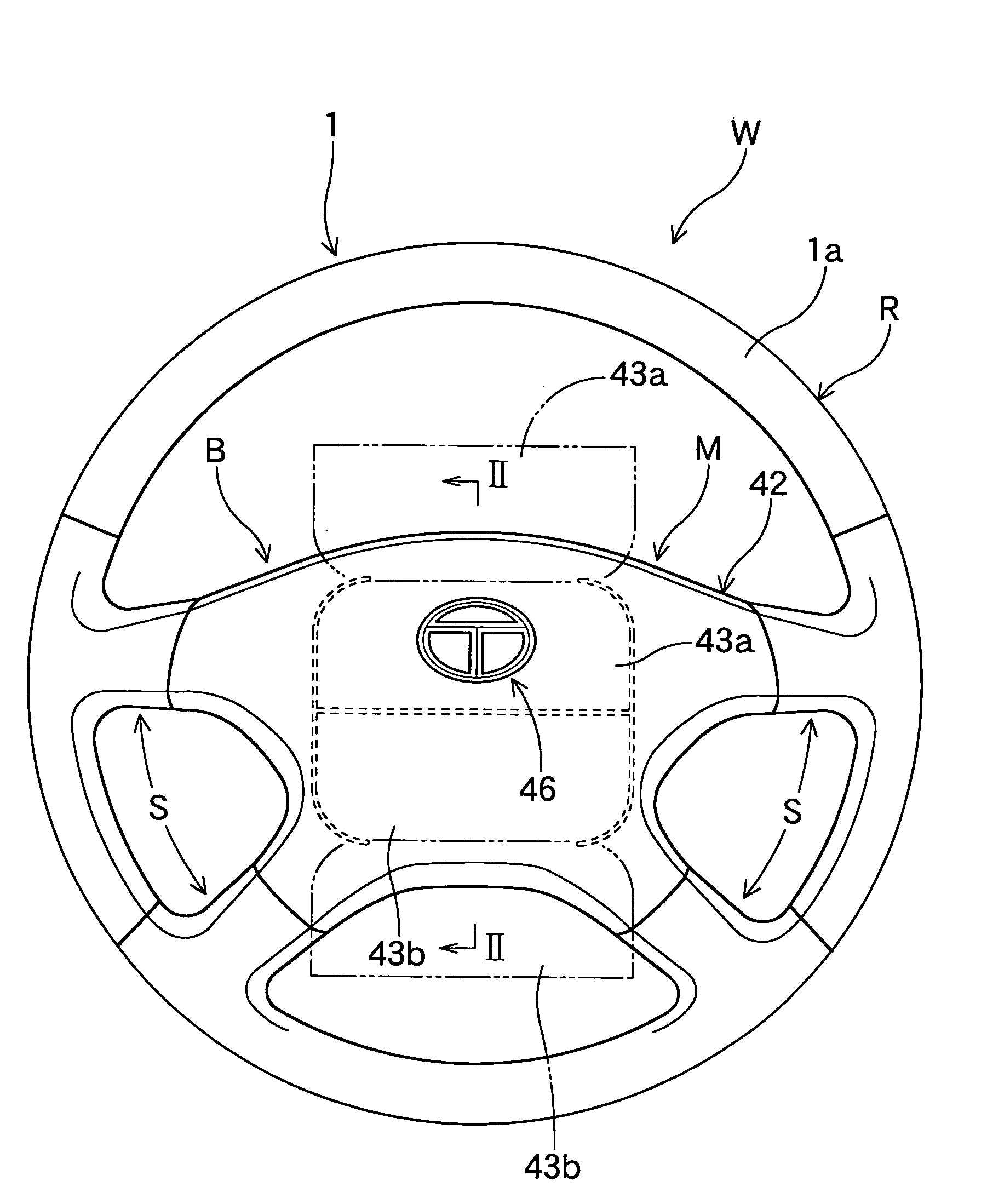
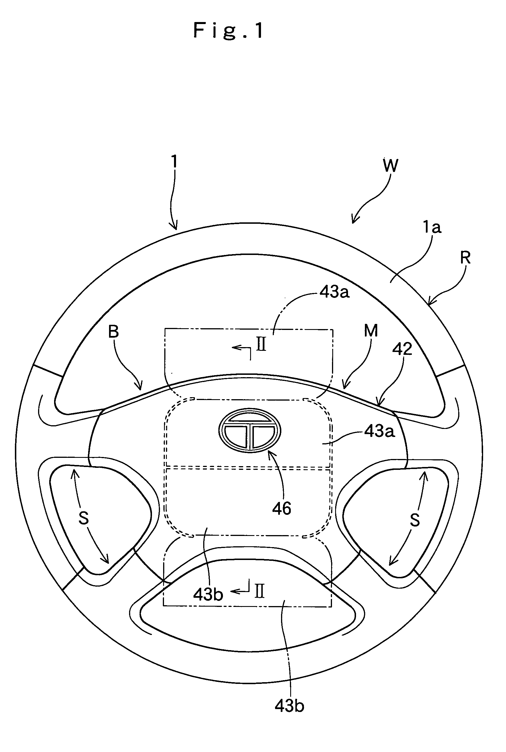
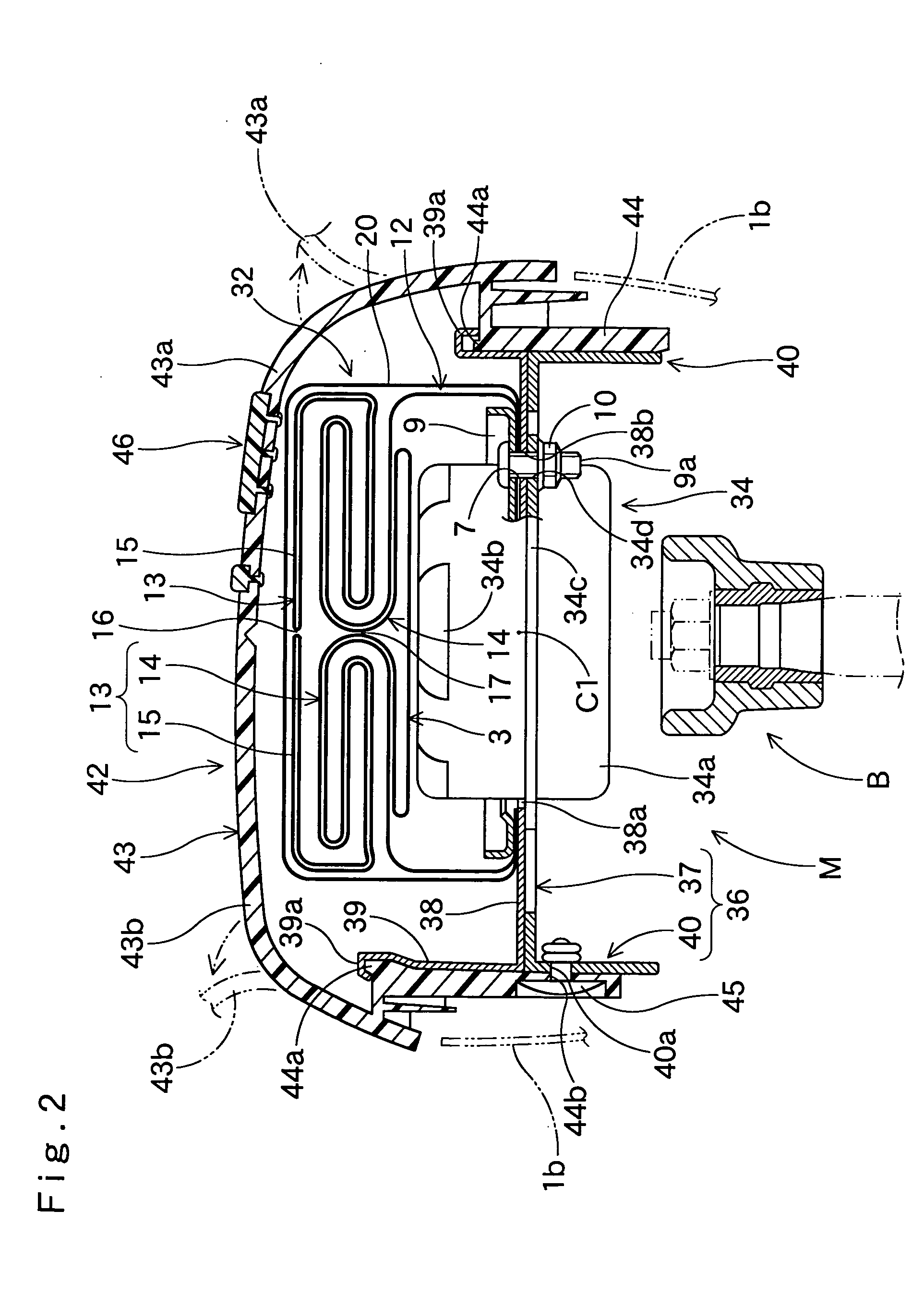
[0034]FIGS. 1 and 2 illustrate an airbag device M for steering wheel according to the present invention. Unless otherwise specified, front-rear, up-down, and left-right directions in this specification are based on a steering wheel W mounted on a vehicle and being steered straight forward. Specifically, up-down is defined by up-down along axial direction of unillustrated steering shaft with which the steering wheel W is to be assembled. Front-rear is defined by vehicle's front-rear direction which is perpendicular to the axial direction of the steering shaft, and left-right is defined by vehicle's left-right direction which is perpendicular to the axial ...


PUM


Abstract

An airbag device according to the present invention includes an airbag folded and housed in the shape of folded-up body, and an airbag wrapping member for keeping the folded-up configuration of the airbag. The folded-up body is formed by bringing both ends of the airbag close to a base line, such that the folded-up body is symmetric with respect to the base line. The wrapping member includes a breakable portion in a region above the base line. The breakable portion includes a plurality of apertures each of which is located across the base line as to extend toward both sides from the base line, and connecting portions for connecting adjacent apertures into a larger opening upon breakage. The connecting portions disposed by the side of both ends of each of the apertures are located in opposite sides of the base line. The wrapping member further includes two cut-out portions in edges of a cover portion in a direction along the base line.

Description

[0001] The present application claims priority from Japanese Patent Application No. 2004-206782 of Ishiguro et al., filed on Jul. 14, 2004, the disclosure of which is hereby incorporated into the present application by reference. BACKGROUND OF THE INVENTION [0002] 1. Field of the Invention [0003] The present invention relates to an airbag device including a bag-shaped airbag which is, when housed, folded into a folded-up body having a generally rectangular parallelepiped shape, and an airbag wrapping member mounted around the folded-up body to keep the folded-up configuration. [0004] 2. Description of Related Art [0005] In the prior art, Japanese Patent No. 3467114 discloses an airbag device including an airbag which is folded into a folded-up body with reference to a straight base line running through a center of a gas inlet port along a plane of the inlet port above the inlet port. The folded-up body is formed by, from a state right before completely folded-up configuration, bring...

Claims


Application Information

Patent Timeline
Patent Type & Authority Applications(United States)
IPC IPC(8): B60R21/16B60R21/201
CPCB60R21/201B60R21/237B60R21/2035
Inventor ISHIGURO, NAOHIKOKIKUTA, MITSUHIROMAEKUBO, YOSHIAKI
Owner TOYODA GOSEI CO LTD
Learn More