Systems and methods for incrementally updating a pose of a mobile device calculated by visual simultaneous localization and mapping techniques

a mobile device and localization technology, applied in the field of navigation of mobile devices, can solve the problems of inability to use preexisting maps, laborious, and laborious, and achieve the effects of improving the accuracy of the localization system, reducing and increasing the difficulty of manual mapping

Active Publication Date: 2006-01-19
IROBOT CORP
View PDF19 Cites 107 Cited by
  • Summary
  • Abstract
  • Description
  • Claims
  • Application Information

AI Technical Summary

Benefits of technology

[0014] One embodiment is a method of updating a map for autonomous localization and mapping for a device, where the method includes: receiving an indication that a landmark has been observed, where the landmark is associated with a landmark pose, and where the map comprises one or more landmarks; predicting a first device pose based on a change in pose from a prior update to device pose, wherein the change in pose is computed at least partly from dead reckoning data; predicting a second device pose based on a visual measurement relative to the observed landmark and based on a stored estimate of landmark pose; predicting a new pose for the device based on at least one of the first device pose and the second device pose; and using a statistical filter to update the corresponding landmark pose estimate based at least partly on the new device pose.
[0015] Another embodiment is a circuit for updating a map for autonomous localization and mapping for a device, where the circuit includes: a circuit configured to receive an indication that a landmark has been observed, where the landmark is associated with a landmark pose, and where the map comprises one or more landmarks; a circuit configured to predict a first device pose based on a change in pose from a prior update to device pose, wherein the change in pose is computed at least partly from dead reckoning data; a circuit configured to predict a second device pose based on a visual measurement relative to the observed landmark and based on a stored estimate of landmark pose; a circuit configured to predict a new pose for the device based on at least one of the first device pose and the second device pose; and a statistical filter that updates the corresponding landmark pose estimate based at least partly on the new device pose.
[0016] Another embodiment is a computer program embodied in a tangible medium for updating a map for autonomous localization and mapping for a device, where the computer program includes: a module with instructions configured to receive an indication that a landmark has been observed, where the landmark is associated with a landmark pose, and where the map comprises one or more landmarks; a module with instructions configured to predict a first device pose based on a change in pose from a prior update to device pose, wherein the change in pose is computed at least partly from dead reckoning data; a module with instructions configured to predict a second device pose based on a visual measurement relative to the observed landmark and based on a stored estimate of landmark pose; a module with instructions configured to ...

Problems solved by technology

Such “pure” localization systems are disadvantageous because generating a map via manual techniques is a relatively difficult, labor-intensive, and specialized task.
For example, the rearranging of furniture in a room can render a preexisting map unusable.
As a result, maps in pure localization systems are subject to relatively frequent and costly updates such that the map accurately represents its surroundings.
Such laser rangefinder techniques, while accurate, are relatively unreliable in dynamic ...

Method used


Image

  • Systems and methods for incrementally updating a pose of a mobile device calculated by visual simultaneous localization and mapping techniques
  • Systems and methods for incrementally updating a pose of a mobile device calculated by visual simultaneous localization and mapping techniques
  • Systems and methods for incrementally updating a pose of a mobile device calculated by visual simultaneous localization and mapping techniques

Examples


Embodiment Construction

[0052] Although this invention will be described in terms of certain preferred embodiments, other embodiments that are apparent to those of ordinary skill in the art, including embodiments that do not provide all of the benefits and features set forth herein, are also within the scope of this invention.

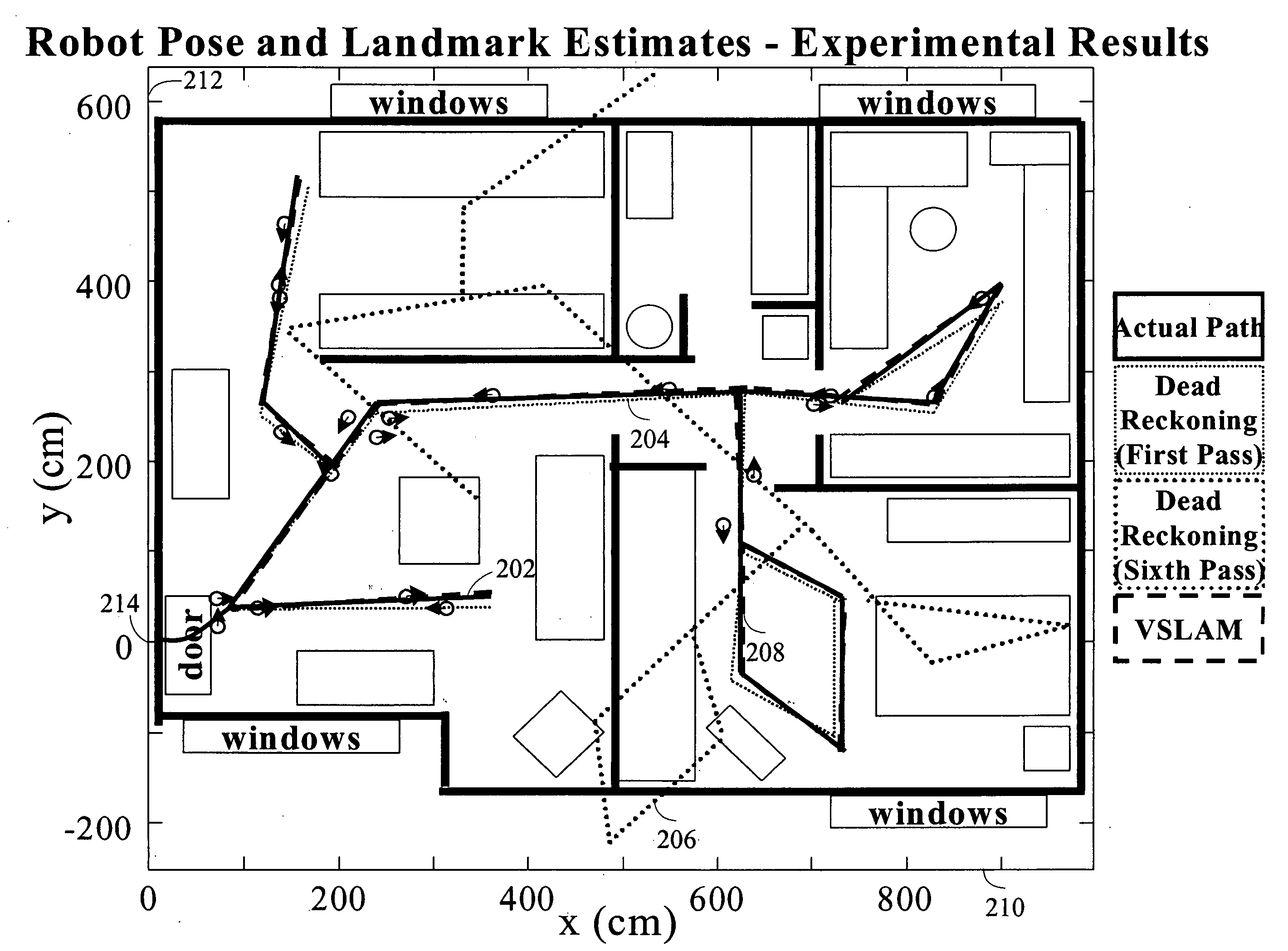
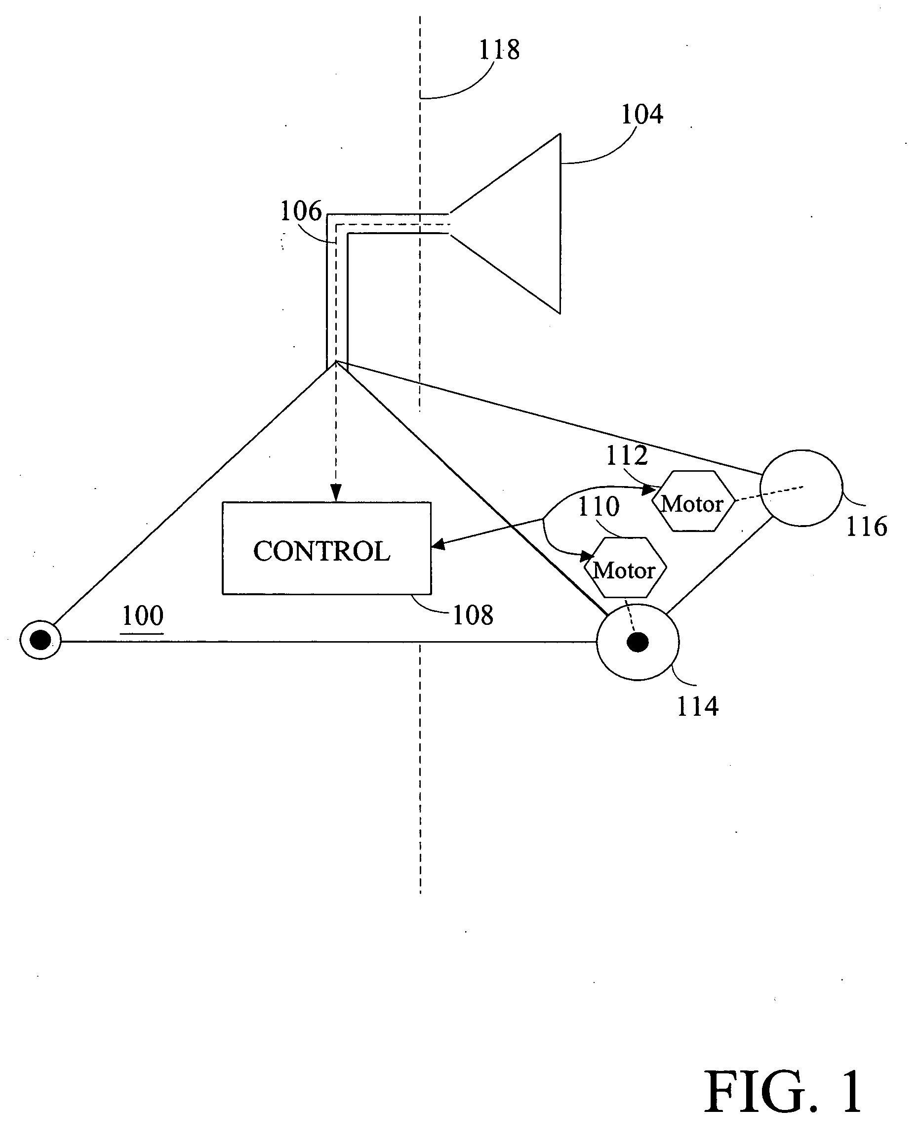
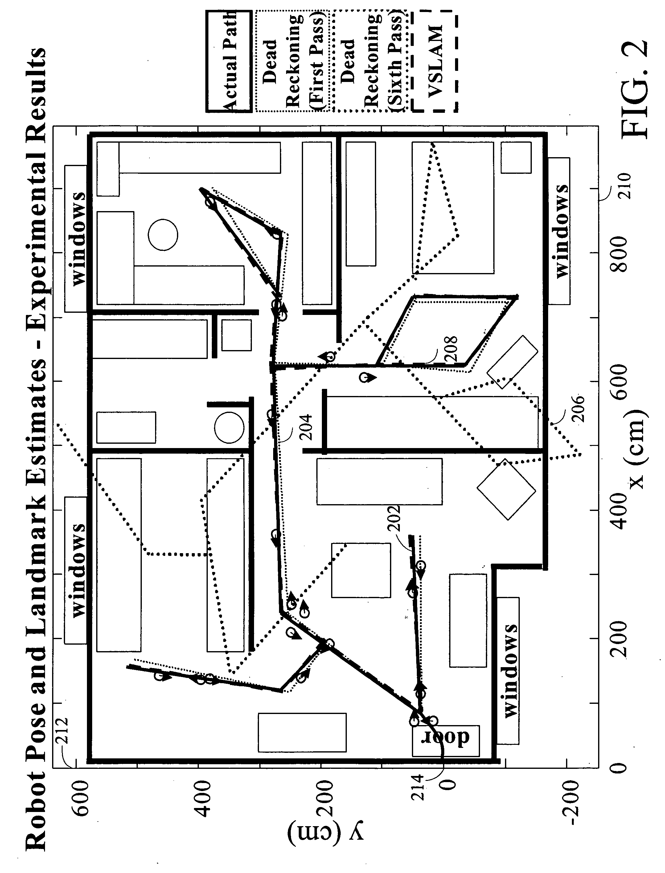
[0053] Embodiments of the invention advantageously use one or more visual sensors and one or more dead reckoning sensors to process Simultaneous Localization and Mapping (SLAM). The combination of SLAM with visual sensors will hereafter be referred to as VSLAM. Advantageously, such visual techniques can be used by a vehicle, such as a mobile robot, to autonomously generate and update a map. In one embodiment, VSLAM is advantageously used by a portion of a vehicle, such as by an “arm” of a vehicle. In contrast to localization and mapping techniques that use laser rangefinders or other range-based devices or sensors, the visual techniques are economically practical in a wide range of a...


PUM


Abstract

The invention is related to methods and apparatus that use a visual sensor and dead reckoning sensors to process Simultaneous Localization and Mapping (SLAM). These techniques can be used in robot navigation. Advantageously, such visual techniques can be used to autonomously generate and update a map. Unlike with laser rangefinders, the visual techniques are economically practical in a wide range of applications and can be used in relatively dynamic environments such as environments in which people move. One embodiment further advantageously uses multiple particles to maintain multiple hypotheses with respect to localization and mapping. Further advantageously, one embodiment maintains the particles in a relatively computationally-efficient manner, thereby permitting the SLAM processes to be performed in software using relatively inexpensive microprocessor-based computer systems.

Description

RELATED APPLICATION [0001] This application claims the benefit under 35 U.S.C. § 119(e) of U.S. Provisional Application No. 60 / 434,269, filed Dec. 17, 2002, and U.S. Provisional Application No. 60 / 439,049, filed Jan. 09, 2003, the entireties of which are hereby incorporated by reference. Appendix A [0002] Appendix A, which forms a part of this disclosure, is a list of commonly owned copending U.S. patent applications. Each one of the applications listed in Appendix A is hereby incorporated herein in its entirety by reference thereto.BACKGROUND OF THE INVENTION [0003] 1. Field of the Invention [0004] The invention generally relates to navigation of mobile devices. In particular, the invention relates to localization and mapping techniques that can be used in vehicles, such as in mobile robots. [0005] 2. Description of the Related Art [0006] Mobile robots are becoming more and more commonplace in society. It will be understood that these robots can be embodied in a variety of forms, s...

Claims


Application Information

Patent Timeline
IPC IPC(8): G08G1/123G01C21/26G05D1/02
CPCG01C21/12G06T2207/30204G05D1/024G05D1/0242G05D1/0246G05D1/0248G05D1/0272G05D1/0274G05D1/0278G05D2201/0207G05D2201/0215G05D1/0231Y10S901/01Y10S901/46Y10S901/47Y10S901/50G06T7/0044G06T7/0065G05D1/0234G06T7/74G06T7/55G01C21/206G06T7/70
Inventor KARLSSON, L. NIKLASPIRJANIAN, PAOLOGONCALVES, LUIS FILIPE DOMINGUESBERNARDO, ENRICO DI
Owner IROBOT CORP
Why Eureka
Try Eureka