Postage meter system having a controlled level of ink

a postage meter and control level technology, applied in the field of mail handling, can solve the problems of still suffering from a drawback as regards managing the filling of the print module with ink, affecting the accuracy of postage meter printing, so as to simplify the physical structure, avoid fraudulent filling, and cost less.

a postage meter and control level technology, applied in the field of mail handling, can solve the problems of still suffering from a drawback as regards managing the filling of the print module with ink, affecting the accuracy of postage meter printing, so as to simplify the physical structure, avoid fraudulent filling, and cost less.

US20060012626A1Inactive Publication Date: 2006-01-19NEOPOST TECH SA

Image

  • Postage meter system having a controlled level of ink
  • Postage meter system having a controlled level of ink
  • Postage meter system having a controlled level of ink

Examples


Embodiment Construction

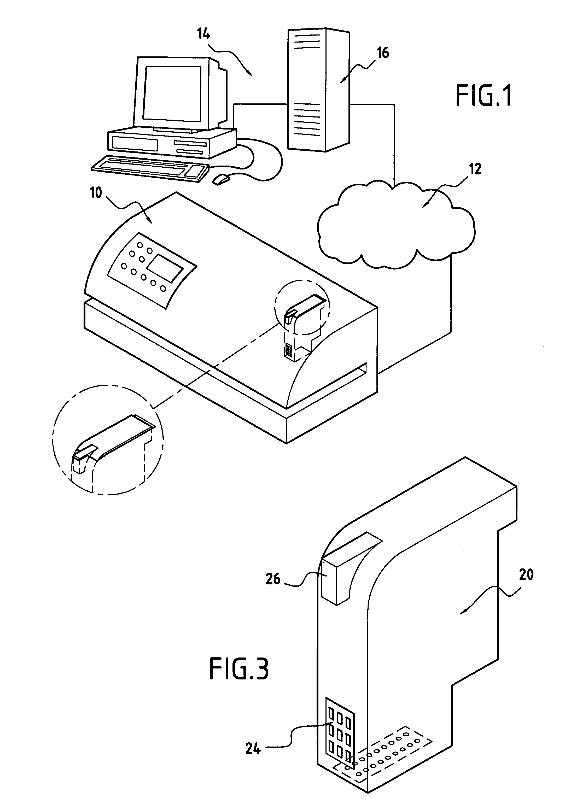
[0024]FIG. 1 shows the architecture of a mail franking system that implements the present invention. The system conventionally includes a postage meter for franking mail items 10 that is connected via a wired communications network 12 to a remote computer server 14 of the postage meter dealer or of the postal administration, the server incorporating a database 16. The network can be of the analogue type (of the Public Switched Telephone Network (PSTN) type) or of the digital type (of the Integrated Services Digital Network (ISDN) type), and the link between the meter and the server is a link that is made secure by enciphering or signing so as to make it possible, in particular, to give new credit to the postage meter from the computer server.

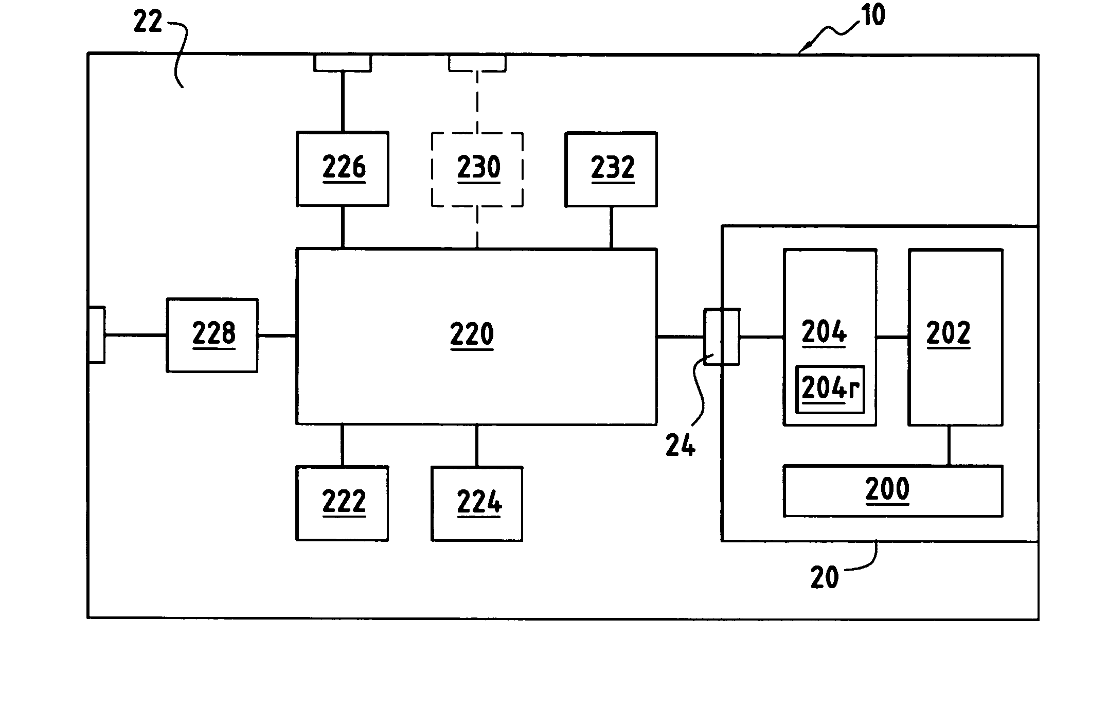
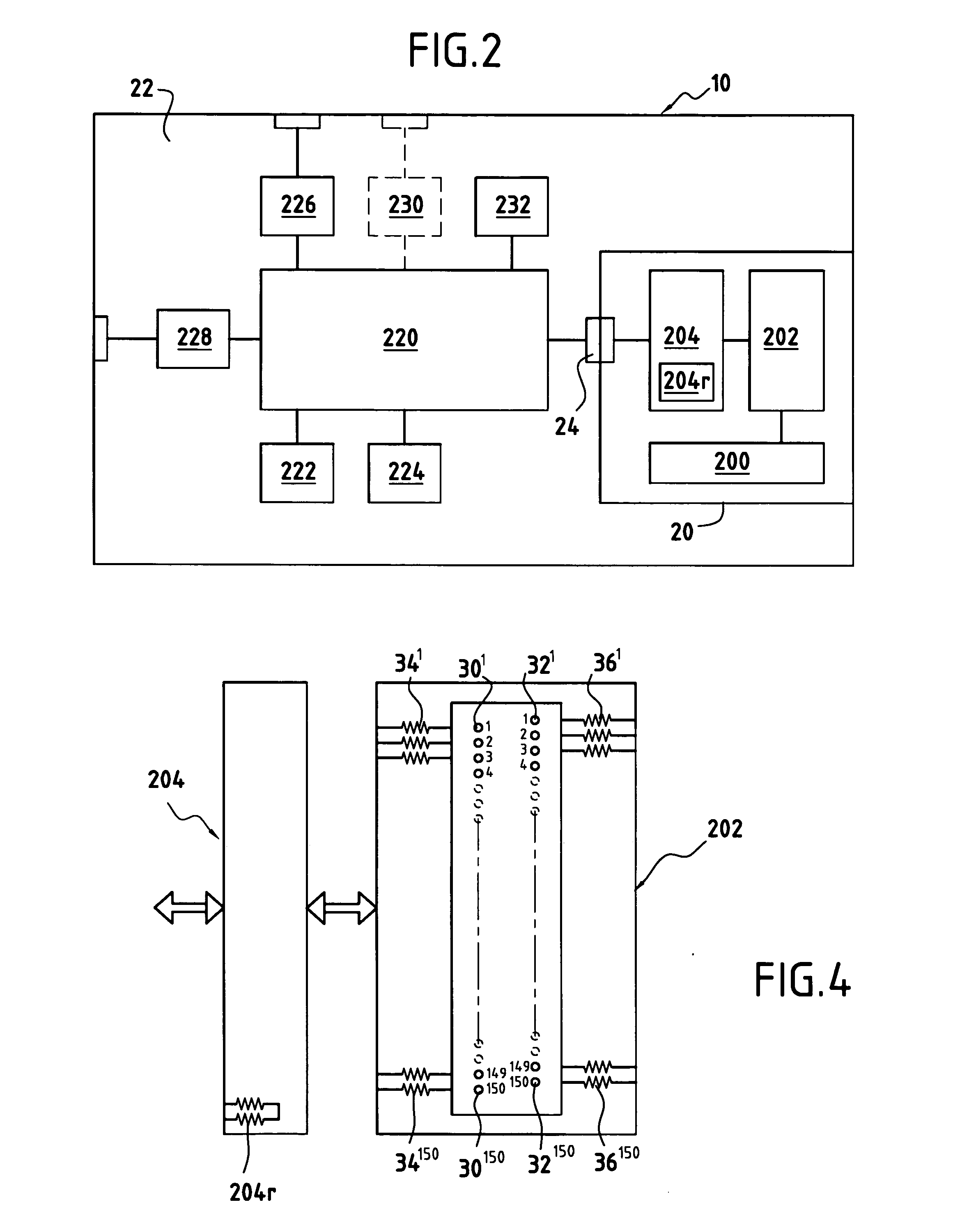
[0025]FIG. 2 is a simplified block diagram showing the electronic structure of the postage meter 10. In order to enable the invention to be understood better, the electronic circuits relating to controlling the motors for conveying the mail ite...


PUM


Abstract

A method of disabling operation of a disposable print module that has an ink reservoir and a plurality of ink ejection nozzles including unused nozzles, and that serves to be mounted on a base of a postage meter, the method including the following steps: forming, in a prior step, a residual ink level counter using a determined first group of the unused nozzles; determining the volume of ink consumed; destroying one of the unused nozzles of the residual ink level counter every time the print module is mounted on a different postage meter base; destroying one of the unused nozzles of ink consumed exceeds a predetermined ink level; and disabling operation of the print module when all of the unused nozzles of the residual ink level counter have been destroyed.

Description

TECHNICAL FIELD [0001] The present invention relates to the field of mail handling, and more particularly to the field of postage meters or “franking machines” of the kind including a disposable digital inkjet print module. PRIOR ART [0002] Postage meters having disposable print modules are well known, in particular from European Patent Application EP 0 875 862. Such a print module conventionally has an array of resistors, the resistances of which correspond to an identity number. That number, which is, in general, attributed by the manufacturer of the module, e.g. the American supplier Hewlett Packard, serves to implement a security process for making printing secure and that is needed for limiting fraud, which is always possible because of the monetary value attributed to the postal imprint. [0003] European Patent Application EP 1 132 868 illustrates such a security process performed on a standard print module in order to make it compatible with use in mail handling. That document...

Claims


Application Information

Patent Timeline
19 Jan 2006
Publication
US20060012626A1
IPC
B41J29/393
CPC
B41J2/17546; B41J2/17566; G07B2017/00556; G07B17/00508; G07B2017/00532; B41J29/393
Inventors
NLEND, BENEDICTE; RAY, DANY