
Transient protector circuit for multi-phase energized power supplies

Inactive Publication Date: 2006-01-19
ELSTER ELECTRICTY LLC
View PDF4 Cites 74 Cited by
  • Summary
  • Abstract
  • Description
  • Claims
  • Application Information

AI Technical Summary

Benefits of technology

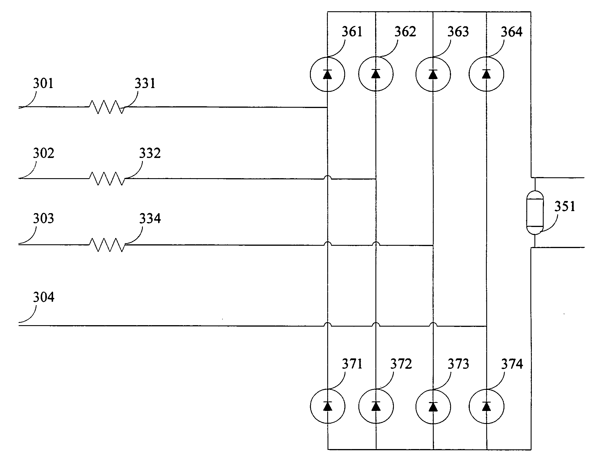
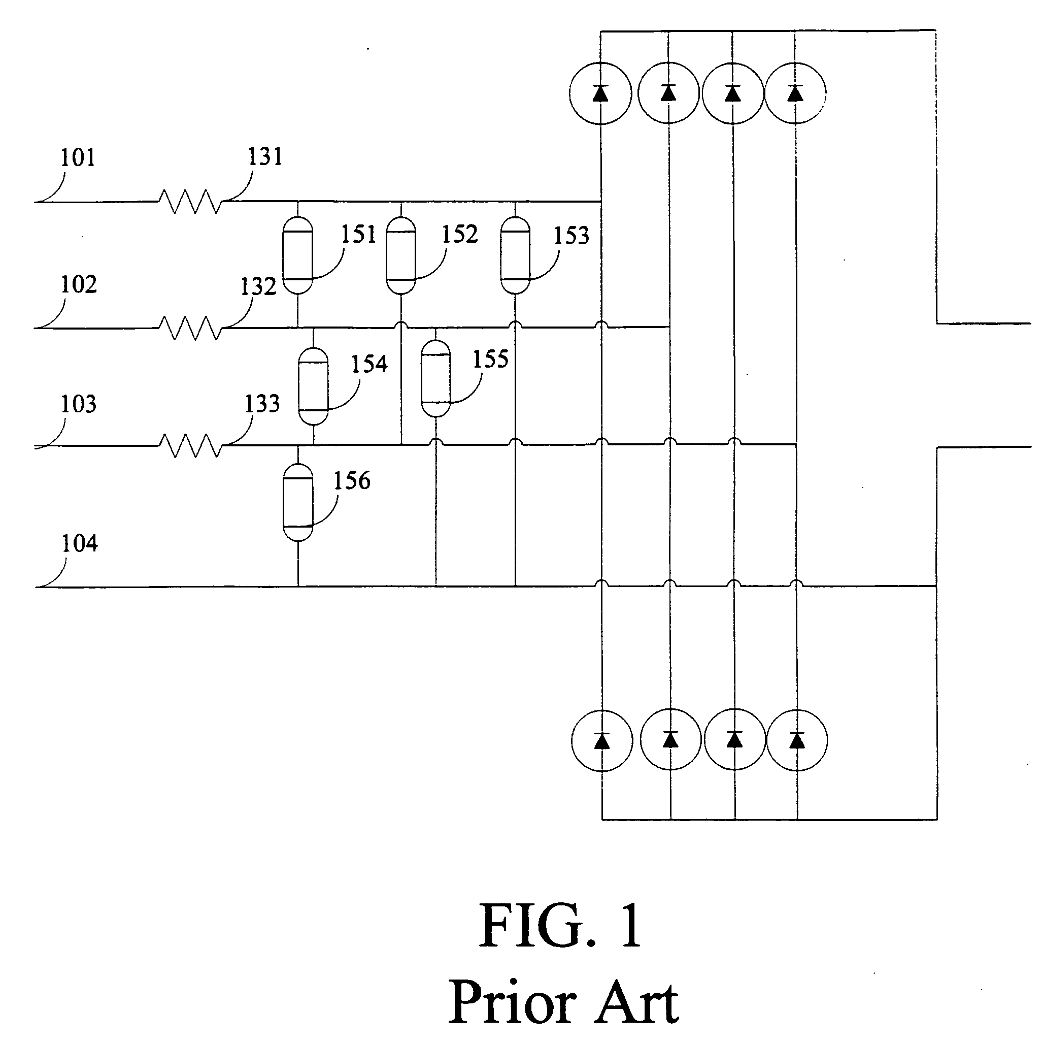
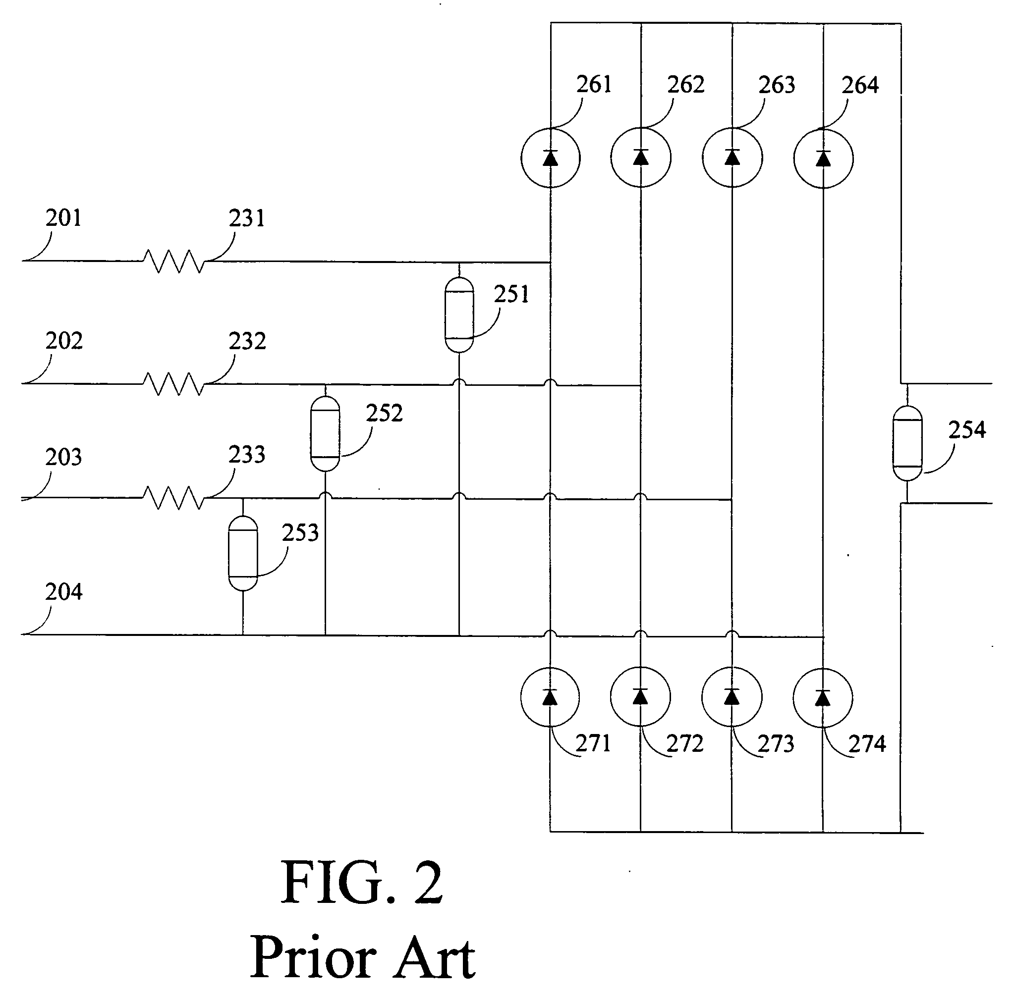
[0017] The present invention is directed to circuits and systems for use in multi-phase power supplies for the control of transient currents. The present invention reduces transient currents to a level benign to succeeding power supply stages, while at the same time being less expensive and smaller than prior art circuits and systems such as those described in FIGS. 1 and 2.
[0018] According to aspects of the invention, phase to phase and phase to neutral MOVs are replaced with a single DC power supply connected MOV. Phase to phase transient currents are limited by resistors that are connected in series to each of the three phase inputs. Comprising a single DC connected MOV, an exemplary circuit provides protection from transients between any of the four inputs. The phase to phase and the phase to neutral transient currents are routed, desirably using diodes, through a single MOV connected between the positive and negative output terminals of the DC power supply. The single MOV is preferably the same size as the MOVs used in prior art circuits. Exemplary circuits and systems according to the present invention offer a net cost savings and can be implemented using significantly less circuit board area than prior methods.

Problems solved by technology

The increasing usage of sensitive solid state devices in modem electrical systems, particularly computers, has given rise to concerns about transients.
These concerns stem from the fact that the solid state devices are very susceptible to stray electrical transients which may be present in a distribution system.
The problem of providing transient protection is compounded for a supply energized from multiple phases.
However, these prior art circuits have significant drawbacks.
For example, the cost of MOVs are high.
MOVs are significantly more expensive than the other components making up the circuit.
Moreover, MOVs of sufficient strength to reduce transients in a power supply are typically very large, especially when compared to the other components in the circuits, such as resistors and capacitors.

Method used


Image

  • Transient protector circuit for multi-phase energized power supplies
  • Transient protector circuit for multi-phase energized power supplies
  • Transient protector circuit for multi-phase energized power supplies

Examples


Embodiment Construction

[0026]FIG. 3 illustrates a circuit diagram of an exemplary circuit for the prevention of transients in a three phase power supply in accordance with the present invention. The circuit utilizes only one MOV 351. This reduction in the number of MOVs results in a considerable saving of both money and circuit space. There are four inputs into the circuit: A phase, B phase, C phase, and neutral, shown in FIG. 3 as inputs 301, 302, 303, and 304, respectively. While FIG. 3 is described with reference to a three phase power supply, those skilled in the art will appreciate that the circuit described is extendable for use in power supplies with more than three phases.

[0027] The circuit employs one MOV 351 to protect against high energy transient voltages between the phases and between each of the phases and neutral. MOV 351 is connected between the terminals of the DC output. MOV 351 connects, through diodes 361, 362, 363, 364, 371, 372, 373, 374, each of the three phases and each of the thr...


PUM


Abstract

Circuits and systems are used in multi-phase power supplies for the prevention of transient currents. Phase to phase and phase to neutral metal oxide varistors (“MOV”) are replaced with a single DC power supply connected MOV. Transient currents are limited by resistors that are connected in series to each of the three phase inputs. Comprising a single DC connected MOV, protection from transients between any of the four inputs is provided. The phase to phase and the phase to neutral transient currents are routed, using diodes, through a single MOV connected between the positive and negative input terminals of the DC power supply.

Description

FIELD OF THE INVENTION [0001] This invention relates in general to the field of high energy transient protection. More particularly, this invention relates to the design of circuitry for use in power supplies to protect against high energy transients. BACKGROUND OF THE INVENTION [0002] The increasing usage of sensitive solid state devices in modem electrical systems, particularly computers, has given rise to concerns about transients. These concerns stem from the fact that the solid state devices are very susceptible to stray electrical transients which may be present in a distribution system. Transients in an electrical circuit result from the sudden release of previously stored energy. The severity of, and hence the damage caused by, transients depends on their frequency of occurrence, the peak transient currents, the voltages present, and their wave shapes. [0003] It is common practice for power supplies to include circuitry that provides protection from high energy transients pr...

Claims


Application Information

Patent Timeline
IPC IPC(8): H02H3/22
CPCH02H9/04H02H1/04H02H7/125H02H9/02H02H9/044
Inventor MURPHY, MICHAEL A.
Owner ELSTER ELECTRICTY LLC
Learn More