Fluorescent lighting fixtures

a technology of fluorescent lamps and lighting fixtures, applied in the direction of lighting and heating apparatus, coupling device connections, lighting support devices, etc., can solve the problems of affecting the illumination effect, so as to improve the connection structure, improve the illumination effect, and enhance the appearan

Inactive Publication Date: 2006-01-19
FEELUX CO LTD
View PDF10 Cites 47 Cited by
  • Summary
  • Abstract
  • Description
  • Claims
  • Application Information

AI Technical Summary

Benefits of technology

[0022] Accordingly, the present invention has been made to solve the above problems, and it is an object of the present invention is to provide fluorescent lighting fixtures, which can be aligned regularly and in series, and prevent any intervals from being formed between fluorescent lamps, thereby providing beautiful outward appearance, increasing the illumination effect, and improving an connection structure more firmly.

Problems solved by technology

But, in this case, the conventional method has a problem in that illumination is distorted since the fluorescent lamps 20 are not aligned in a line.
Moreover, when the fluorescent lamp 20 is separated from the socket 10, it may cause an unexpected accident as well as damage of the fluorescent lamp 20.

Method used


Image

  • Fluorescent lighting fixtures
  • Fluorescent lighting fixtures
  • Fluorescent lighting fixtures

Examples


Embodiment Construction

[0036] Reference will now be made in detail to the preferred embodiments of the present invention, examples of which are illustrated in the accompanying drawings.

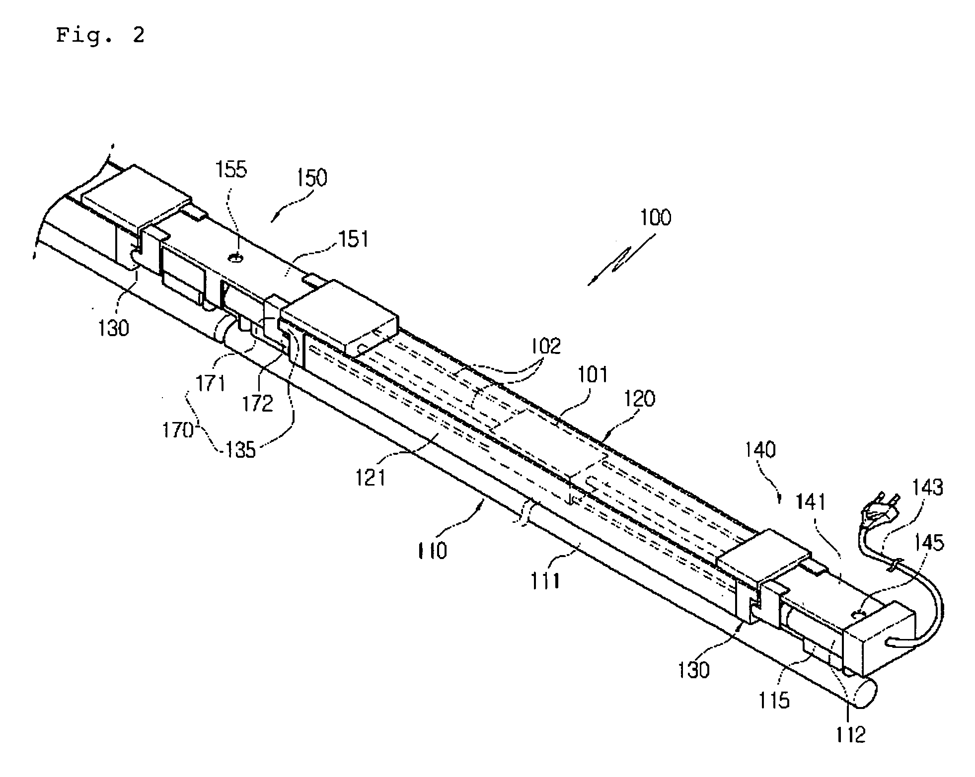
[0037]FIG. 2 is a perspective view of a fluorescent lighting fixture according to a preferred embodiment of the present invention, FIG. 3 is an exploded perspective view of the fluorescent lighting fixture according to the present invention, FIG. 4 is a perspective view of a modification of a connector according to the present invention, and FIGS. 5 and 6 are perspective views of modifications of a fluorescent lamp according to the present invention.

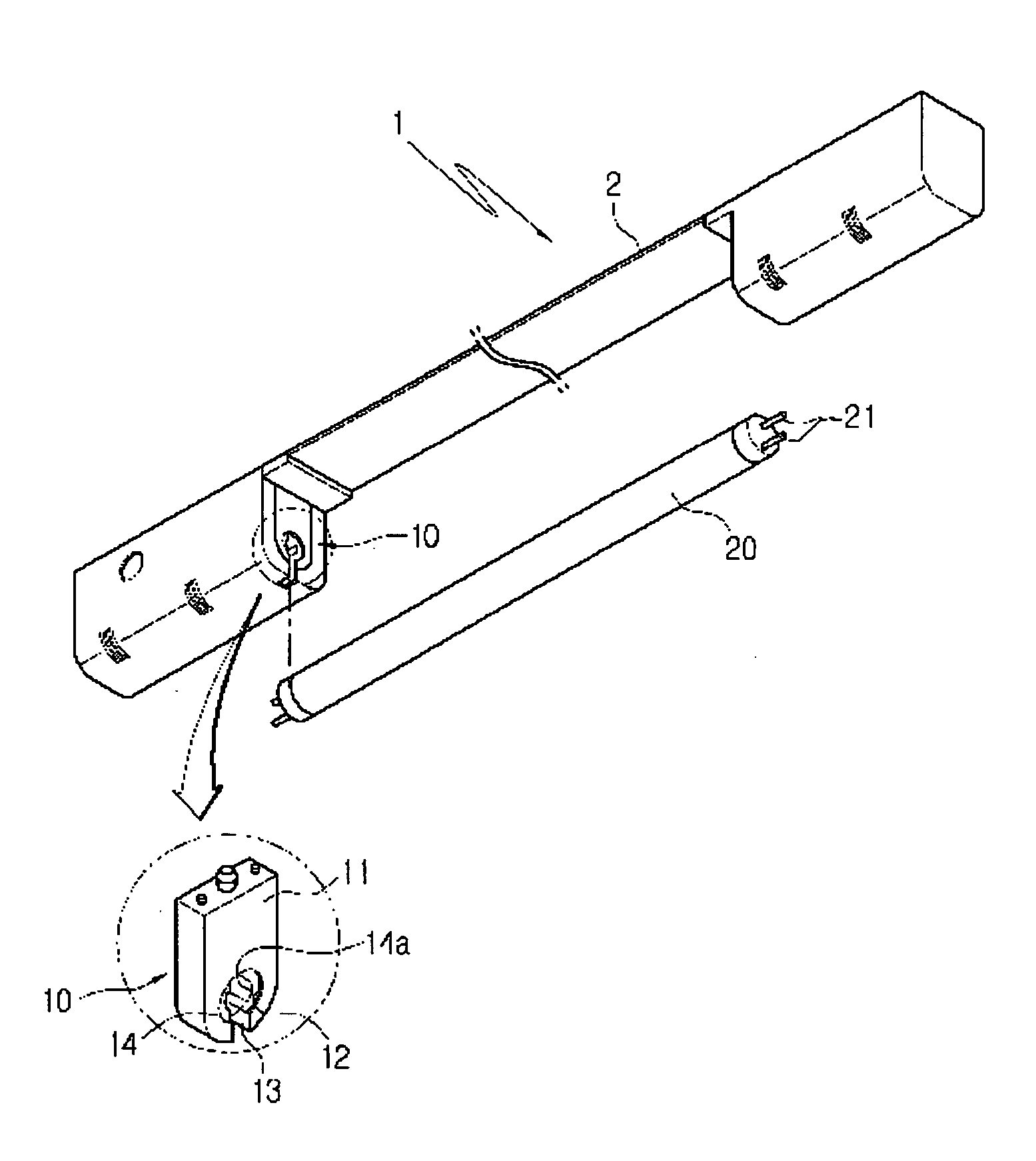
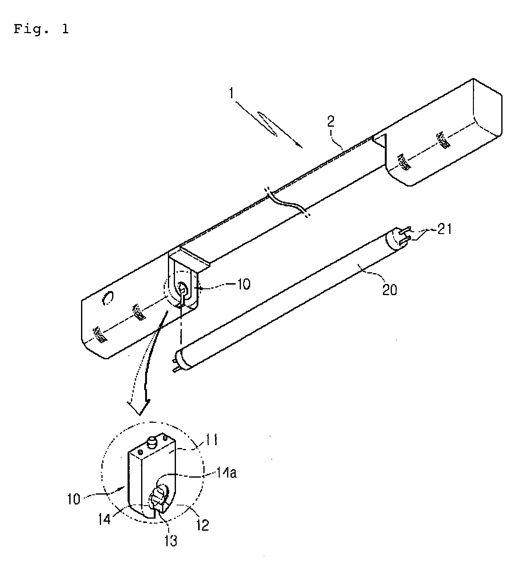
[0038] As shown in the drawings, the fluorescent lighting fixture 100 according to the present invention includes a fluorescent lamp 110, a body 120 bent in a predetermined shape and serving as a reflection plate, and sockets 130 connected and fixed at both ends of the body 120 for supplying power source to the fluorescent lamp 110.

[0039] First, the fluorescent lamp 110 inclu...


PUM


Abstract

The present invention relates to fluorescent lighting fixtures, which are aligned in series at regular intervals, which are easily connected one another, and which prevent discontinuation of illumination occurring between fluorescent lamps. The fluorescent lighting fixture includes: a fluorescent lamp having a tube type lamp body, auxiliary tubes mounted at the tops of both ends of the lamp body, and terminal pins inwardly formed at an end of each auxiliary tube; a body having a stabilizer mounted therein for lighting the fluorescent lamp, connection terminals located at both ends thereof at a predetermined interval and electrically connected with the stabilizer; and sockets mounted at both ends of the body, each of the sockets having a support slit formed in the outer surface thereof for fixing and supporting the terminal pins of the fluorescent lamp, and a receiving slit for allowing the terminal pins to be inserted into the support slit.

Description

BACKGROUND OF THE INVENTION [0001] 1. Field of the Invention [0002] The present invention relates to fluorescent lighting fixtures, and more particularly, to fluorescent lighting fixtures, which are aligned in series at regular intervals, which are more easily connected to one another, and which prevent discontinuation of illumination occurring between fluorescent lamps. [0003] In addition, the present invention relates to a fluorescent lamp socket having an improved socket structure, which allows for an easy mounting of the fluorescent lamp, and which can restrict rotation of the fluorescent lamp after the mounting to prevent separation of the fluorescent lamp from the socket, thereby preventing an unexpected accident and reducing damage of the fluorescent lamp. [0004] 2. Background of the Related Art [0005] As shown in FIG. 1, a fluorescent lamp 20, which has been used till now, has terminal pins 21 mounted at both ends thereof, and the fluorescent lamp 20 is mounted to a fluoresc...

Claims


Application Information

Patent Timeline
Patent Type & Authority Applications(United States)
IPC IPC(8): F21S4/00
CPCF21V19/0085F21V21/005H01R33/7692H01R33/0854H01R33/0863F21Y2103/00
Inventor NOH, SHI YOUL
Owner FEELUX CO LTD
Why Eureka
Try Eureka