
Detection of synchronization timing in CDMA receiving apparatus

a synchronization timing and receiving apparatus technology, applied in the direction of electrical apparatus, transmission, transmission monitoring, etc., can solve the problems of reducing the demodulation accuracy of rake combining, unable to detect a large number of paths as finger-assigned paths, and degrading the reception quality, so as to maintain the reception quality

Inactive Publication Date: 2006-01-19
NEC CORP
View PDF10 Cites 5 Cited by
  • Summary
  • Abstract
  • Description
  • Claims
  • Application Information

AI Technical Summary

Benefits of technology

[0031] It is therefore an object of the present invention to provide a CDMA receiving apparatus which is capable of maintaining a reception quality irrespective of a radio wave propagation environment, and to provide a method of detecting synchronization timing in the CDMA receiving apparatus.
[0037] According to the first aspect, a same-path detection time range is selected in accordance with a particular radio wave propagation environment by calculating a delay spread based on path timings and path levels of paths, and paths are selected for assignment to fingers using the same-path detection time range. It is therefore possible to improve the accuracy of detecting synchronization timings for a received signal and to improve the reception quality of the CDMA receiving apparatus.
[0044] According to the second aspect, a delay spread is calculated based on path timings and path levels of paths, and an angle spread is calculated based on directions of arrival and path levels of the paths to select a same-path detection time range and a same-path detection angle range in accordance with a particular radio wave propagation environment, and paths are selected for assignment to fingers using the same-path detection time range and same-path detection angle range. It is therefore possible to improve the accuracy of detecting synchronization timings for received signals, to accurately find directions of arrival of the received signals, and to improve the reception quality of the CDMA receiving apparatus.

Problems solved by technology

On the other hand, however, if paths arrive in a concentrated manner at the same time, a large number of paths cannot be detected as finger-assigned paths.
Therefore, a uniquely set same-path detection time range can cause a lower path detectability factor depending on certain radio wave propagation environments, thus leading to a lower demodulation accuracy in the RAKE combining, and a degraded reception quality.
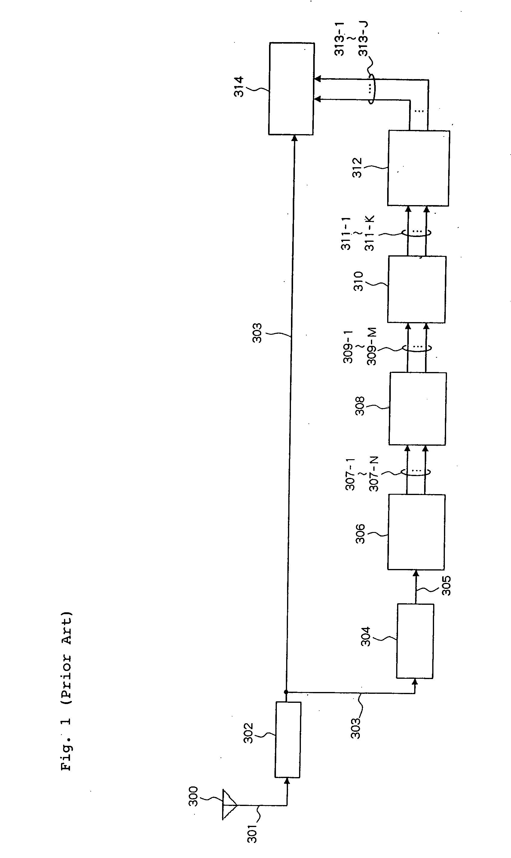
However, since the same-path detection time range in the time direction is uniquely set on the delay profile, the demodulation accuracy becomes lower in the RAKE combining depending on some radio wave propagation environments, resulting in a degraded reception quality, as is the case with the CDMA receiving apparatus illustrated in FIG. 1.
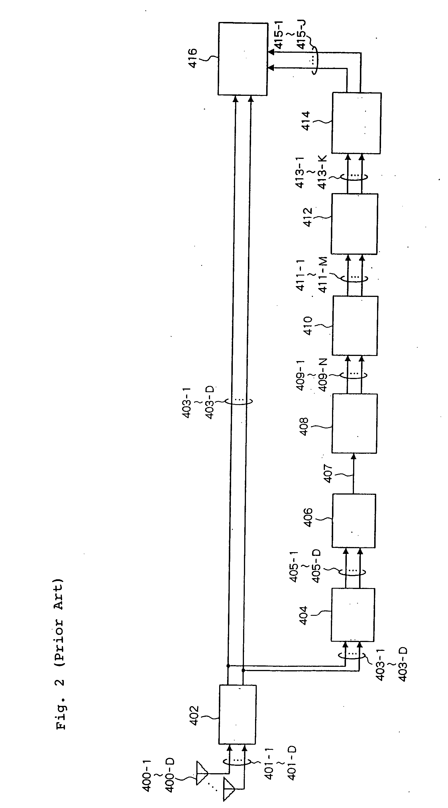
Also, the same-path detection angle range in the angle direction is uniquely set on the angle profile, causing a deterioration in path detection rate, a failure in accurately finding the direction of arrival of a received signal, and a degraded reception quality.
As described above, conventional CDMA receiving apparatuses experience the problem of degraded reception quality due to the same-path detection time range which is uniquely set irrespective of the radio wave propagation environment.

Method used


Image

  • Detection of synchronization timing in CDMA receiving apparatus
  • Detection of synchronization timing in CDMA receiving apparatus
  • Detection of synchronization timing in CDMA receiving apparatus

Examples


first embodiment

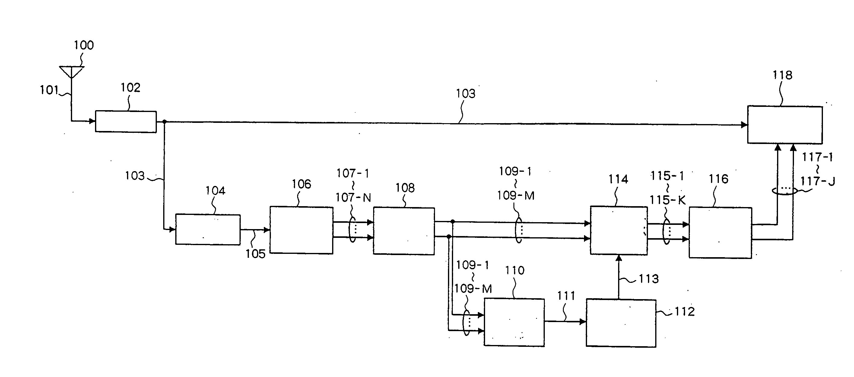
[0054] Referring to FIG. 3, a CDMA receiving apparatus of a first embodiment comprises antenna 100, radio receiver unit 102, correlated power calculation unit 104, path detector unit 106, path level thresholding unit 108, delay spread calculation unit 110, same-path detection time range calculation unit 112, finger-assigned path selector unit 114, finger assignment unit 116, and demodulation processing unit 118.

[0055] Radio receiver unit 102 converts analog radio signal 101 received by antenna 100 to digital baseband signal 103.

[0056] Correlated power calculation unit 104 calculates a correlated value of digital baseband signal 103, and converts the correlated value to a power value to generate delay profile 105.

[0057] Path detector unit 106 detects N peaks on delay profile 105 as paths, and generates timing / level information 107-1-107-N each indicative of a path timing and a path level associated with each of the N detected paths.

[0058] Path level thresholding unit 108 determin...

second embodiment

[0089] A CDMA receiving apparatus of a second embodiment employs array antennas compose of a plurality of antenna elements. The CDMA receiving apparatus of this embodiment calculates not only a delay profile indicative of a correlated power value distribution in the time direction but also an angle profile indicative of a correlated power value distribution in an angle direction, and calculates a same-path detection time range and a same-path detection angle range in the time and angle directions, respectively. In this way, the CDMA receiving apparatus can accurately detect a synchronization timing and an arrival direction of a received signal.

[0090] Referring to FIG. 6, the CDMA receiving apparatus of this embodiment comprises antennas 200-1-200-D composed of antenna elements, radio receiver unit 202, correlated value calculation unit 204, beam former unit 206, path detector unit 208, path level thresholding unit 210, delay spread calculation unit 212, same-path detection time ran...


PUM


Abstract

In a CDMA receiving apparatus according to the present invention, a delay spread calculation unit calculates a delay spread based on timings and levels of paths equal to or higher than a path level threshold, and a same-path detection time range calculation unit calculates a same-path detection time range in accordance with the delay spread. A finger-assigned path selector unit selects finger-assigned paths from paths equal to or higher than the path level threshold starting in order from the one having the highest path, and excludes paths within the same-path detection time range centered at each selected path, from candidates for finger-assigned paths, from the next selection onward. Then, a demodulation processing unit demodulates a received signal using the path timings of the finger-assigned paths as synchronization timings.

Description

BACKGROUND OF THE INVENTION [0001] 1. Field of the Invention [0002] The present invention relates to a CDMA (Code Division Multiple Access) receiving apparatus, and a method of detecting a synchronization timing in the CDMA receiving apparatus. [0003] 2. Description of the Related Art [0004] A CDMA receiving apparatus in accordance with the CDMA communication standard calculates a delay profile indicative of a relative power value distribution in a time direction based on a correlation value of a received signal to a known code sequence, selects a synchronization timing of the received signal by detecting a peak on the calculated delay profile as a path, and demodulates the received signal using the selected synchronization timing (see, for example, JP-A-10-336072 and JP-A-2003-78448 which are hereinafter called “Documents 1, 2” respectively). [0005] In the following, the configuration of a conventional CDMA receiving apparatus of the type mentioned above will be described in detail...

Claims


Application Information

Patent Timeline
Patent Type & Authority Applications(United States)
IPC IPC(8): H04B1/707H04B1/711H04B1/7113H04B1/7117
CPCH04B1/7113H04B17/364H04B1/7117
Inventor OURA, SATOSHIMARUTA, YASUSHI
Owner NEC CORP
Learn More