Method and apparatus for non-destructive testing

a non-destructive testing and material technology, applied in the direction of liquid/fluent solid measurement, machines/engines, instruments, etc., can solve the problems of not being able to easily cover larger specimens, devices are not without disadvantages, and positrons also lose energy in the source material itsel

Inactive Publication Date: 2006-01-19
BATTELLE ENERGY ALLIANCE LLC
View PDF26 Cites 34 Cited by
  • Summary
  • Abstract
  • Description
  • Claims
  • Application Information

AI Technical Summary

Problems solved by technology

Such positrons also lose energy in the source material itself.
While higher energy positrons (e.g., having energies of about 3 MeV) can be obtained via non-isotopic sources, such as the Pelletron at Lawrence-Livermore Laboratories, such devices are also not without their disadvantages.
For example, the positron beams produced by such sources are oft

Method used


Image

  • Method and apparatus for non-destructive testing
  • Method and apparatus for non-destructive testing
  • Method and apparatus for non-destructive testing

Examples


Embodiment Construction

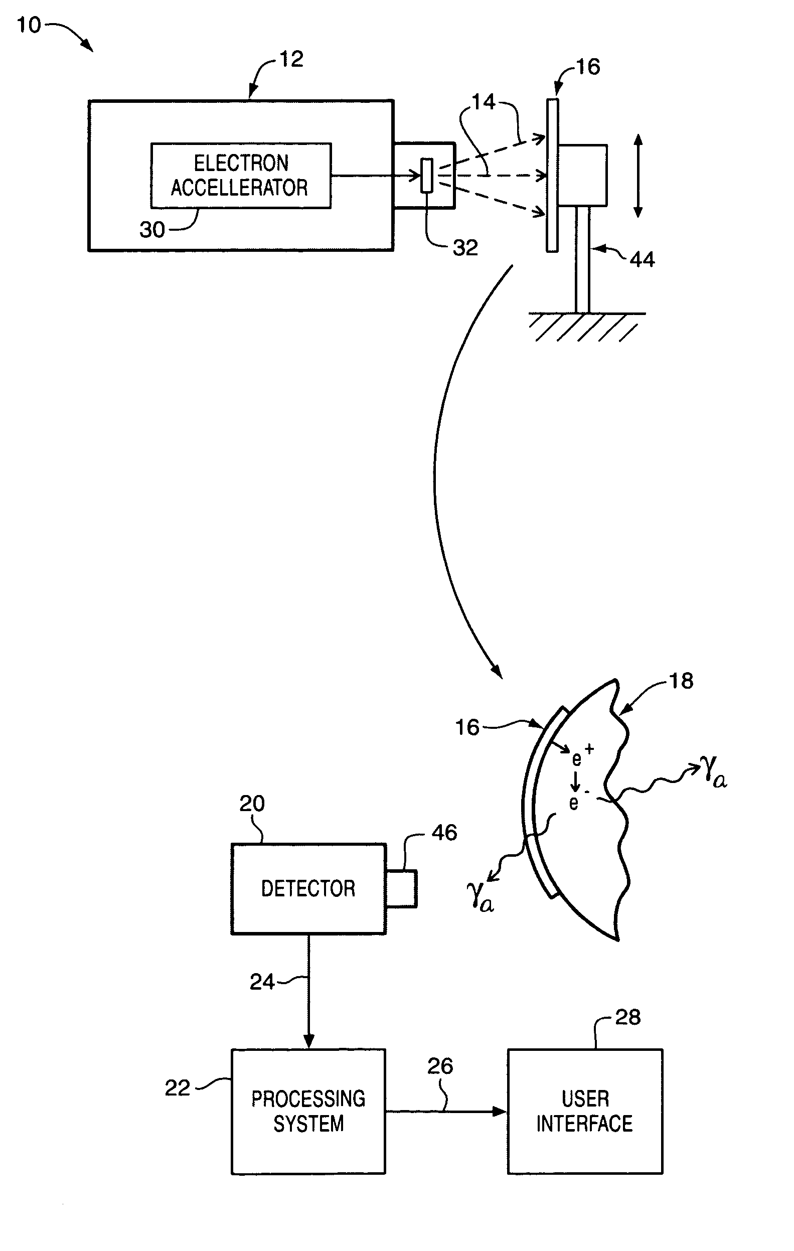
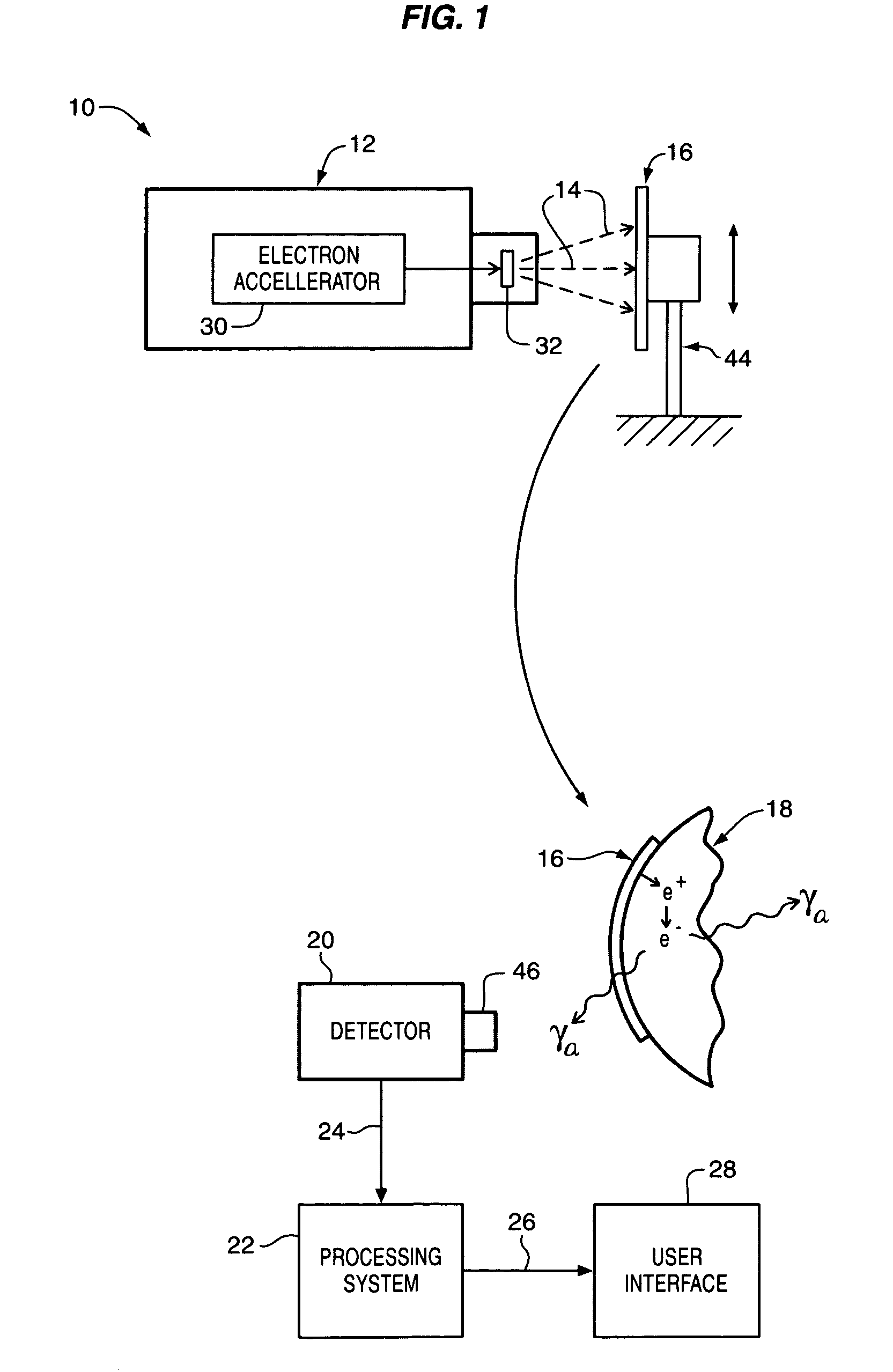
[0018] Non-destructive testing apparatus 10 according to one embodiment of the present invention is illustrated in FIG. 1 and may comprise a photon source 12 for producing photons 14. A source material 16 is positioned adjacent the photon source 12 so that the source material 16 is bombarded by photons 14 from the photon source 12. As will be described in greater detail below, the source material 16 comprises a material that emits positrons e+in response to bombardment of the source material 16 with photons, such as photons 14 from the photon source 12. After being bombarded with photons 14 from the photon source 12, a process referred to herein in the alternative as “photon activation,” the source material 16 may be removed from a position adjacent the photon source 12 and moved to a position adjacent a specimen 18. As will be described in greater detail below, the positrons emitted by the source material 16 may have relatively high energies, e.g., in the range of about 0.5 MeV to ...


PUM


Abstract

Non-destructive testing apparatus may comprise a photon source and a source material that emits positrons in response to bombardment of the source material with photons. The source material is positionable adjacent the photon source and a specimen so that when the source material is positioned adjacent the photon source it is exposed to photons produced thereby. When the source material is positioned adjacent the specimen, the specimen is exposed to at least some of the positrons emitted by the source material. A detector system positioned adjacent the specimen detects annihilation gamma rays emitted by the specimen. Another embodiment comprises a neutron source and a source material that emits positrons in response to neutron bombardment.

Description

CONTRACTUAL ORIGIN OF THE INVENTION [0001] This invention was made with United States Government support under Contract No. DE-AC07-99ID13727 awarded by the United States Department of Energy. The United States Government has certain rights in the invention.TECHNICAL FIELD [0002] This invention relates generally to the testing and evaluation of materials and more specifically to methods and apparatus for performing non-destructive testing of materials using position annihilation. BACKGROUND [0003] Non-destructive material evaluation refers to any of a wide variety of techniques that may be utilized to examine materials for defects and / or evaluate the materials without requiring that the materials first be destroyed. Such non-destructive material evaluation is advantageous in that all materials or products may be tested for defects. After being evaluated, acceptable (e.g., substantially defect-free or with acceptable defect levels) materials may be placed in service, while the defect...

Claims


Application Information

Patent Timeline
IPC IPC(8): G21G1/00
CPCG01N23/227G01N23/221
Inventor AKERS, DOUGLAS W.
Owner BATTELLE ENERGY ALLIANCE LLC
Why Eureka
Try Eureka