Data structure and signaling method for emergency alert message and digital TV receiver

a data structure and signaling method technology, applied in the direction of electrical cable transmission adaptation, simultaneous/sequencial multiple television signal transmission, digital non-picture data transmission, etc., can solve the problem that the emergency alert message signaling method cannot clearly identify whether the details channel to be tuned, and the tuning to the details channel may not be performed properly

Inactive Publication Date: 2006-01-19
LG ELECTRONICS INC
View PDF6 Cites 21 Cited by
  • Summary
  • Abstract
  • Description
  • Claims
  • Application Information

AI Technical Summary

Problems solved by technology

Thus, the conventional emergency alert message signaling method is unable to clearly identify whether the details channel to be tuned is the analog channel or the digital channel represented by the one-part channel number in case that the minor channel number is set to a null value.
So, the tuning to the details channel may be not performed properly.

Method used


Image

  • Data structure and signaling method for emergency alert message and digital TV receiver
  • Data structure and signaling method for emergency alert message and digital TV receiver
  • Data structure and signaling method for emergency alert message and digital TV receiver

Examples


first embodiment

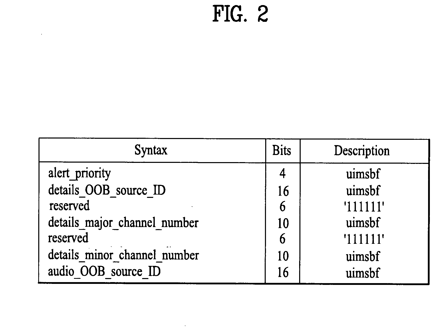
[0038]FIG. 2 is a diagram of a syntax structure describing a processing protocol of an emergency alert message applied to a first embodiment of the present invention, in which parts associated with a channel number of an emergency alert message are shown. An emergency alert message processing protocol cable_emergency_alert( ) in FIG. 2 is defined by an MPEG-2 table format to be compatible with an MPEG-2 transport. The table is divided into at least one section to be transmitted in a transport packet form. Hence, a digital cable broadcast receiver regards the table as a cable_emergency_alert( ) message if a table_ID field value is 0×D8.

[0039] In the emergency alert message processing protocol, an alert_priority field indicates a priority of alert. Namely, a signaling (or processing) of a received emergency alert message is decided (or determined) according to the alert_priority field value. In other words, decided are whether the emergency alert message is unconditionally ignored, w...

second embodiment

[0052] In a second embodiment of the present invention, a field for clearly defining whether a broadcast channel of an emergency alert message is an analog or digital channel in case of an in-band emergency alert system (EAS) is added to the cable_emergency_alert( ) syntax as the emergency alert message processing protocol in FIG. 2. Hence, in case of receiving an emergency alert message transmitted as an in-band signal since the POD module is not loaded, it is facilitated to determine whether a channel of the emergency alert message corresponds to an analog or digital channel.

[0053]FIG. 4 is a diagram of a syntax structure describing a processing protocol of a modified emergency alert message applied to a second embodiment of the present invention, in which parts associated with channel information of an emergency alert message are shown. Referring to FIG. 4, a channel source field, details_channel_source is allocated to one of reserved fields within a cable_emergency_alert( ) syn...


PUM


Abstract

An emergency alert message is included in a cable broadcast signal. The emergency alert message includes major and minor details channel numbers associated with a details channel. A details channel number is configured based on the major details channel number when the minor details channel number is set to a null value. Next, it is tuned to a channel frequency of a digital cable channel corresponding to the details channel number when the details channel number exists in a digital channel number list. Alternatively, the emergency alert message includes a details channel source field which indicates whether a details channel is a digital or an analog channel. Then, it is tuned to a channel frequency of one of a digital cable channel and an analog cable channel based upon a value of the details channel source field.

Description

[0001] This application claims the benefit of the Patent Korean Application No. 10-2004-0055119, filed on Jul. 15, 2004, which is hereby incorporated by reference. BACKGROUND OF THE INVENTION [0002] 1. Field of the Invention [0003] The present invention relates to a data structure and signaling method for an emergency alert message and a digital TV receiver, in which the emergency alert message is transmitted as an in-band signal from a digital cable broadcast transmitter. [0004] 2. Discussion of the Related Art [0005] Generally, a cable set-top box is needed to receive digital cable broadcasts. The digital cable set-top box, which is connected to a cable headend (a sort of a broadcasting station) sending digital cable programs, receives an A / V broadcast program via in-band of a cable frequency band and data broadcasts via out-of-band (OOB). Specifically, the cable set-top box makes bi-directional communications with the headend via OOB. [0006] There are broadcasting protocols such ...

Claims


Application Information

Patent Timeline
Patent Type & Authority Applications(United States)
IPC IPC(8): H04N7/10H04N7/025H04N7/24
CPCH04N7/08H04N21/235H04N21/4181H04N21/435H04N21/8146H04N21/6118H04N21/6143H04N21/6187H04N21/814H04N21/6112H04N7/10
Inventor KIM, BONG SEOKYUN, CHANG SIK
Owner LG ELECTRONICS INC
Why Eureka
Try Eureka