Timing recovery device of digital TV

Inactive Publication Date: 2003-06-24
LG ELECTRONICS INC
View PDF11 Cites 22 Cited by
  • Summary
  • Abstract
  • Description
  • Claims
  • Application Information

AI Technical Summary

Problems solved by technology

The hsync signal and the field synchronizing signal may be interfered by linear distortion of amplitude and ghost resulting from signal reflections off of structures such as buildings and mountains.
G

Method used


Image

  • Timing recovery device of digital TV
  • Timing recovery device of digital TV
  • Timing recovery device of digital TV

Examples


Embodiment Construction

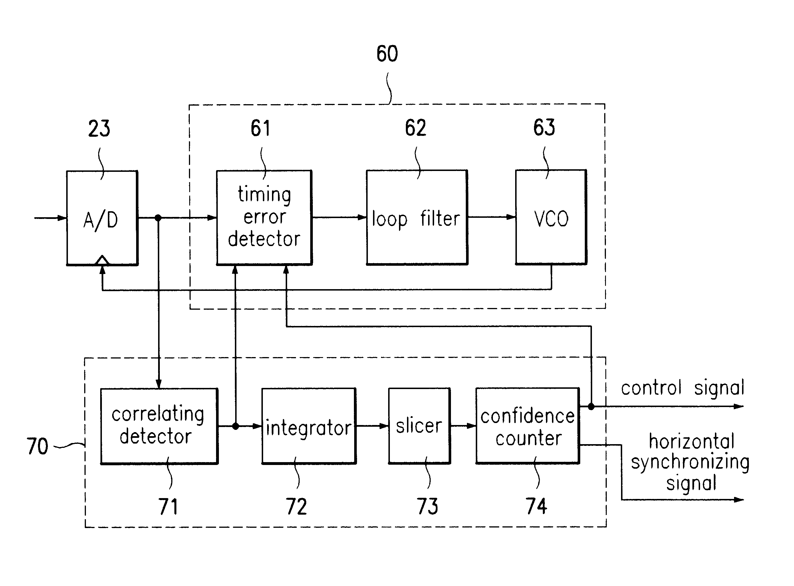
Reference will now be made in detail to the preferred embodiments of the present invention, examples of which are illustrated in the accompanying drawings. FIG. 5 shows a block diagram of a timing recovery device usable in a digital TV according to the present invention, which includes an A / D converter 23, a timing recovery device 60 and a sync signal recovery unit 70, all operatively coupled.

Referring to FIG. 5, the timing recovery device includes a timing error detector 61, a loop filter 62 and a VCO 63 which respectively and generally correspond to elements 31, 32 and 35 described with respect to the timing recovery device of FIG. 3. Similarly, the sync signal recovery unit 70 includes a correlating detector 71, an integrator 72, a slicer 73 and a confidence counter 74 which respectively and generally correspond to elements 41.about.44 described with respect to the sync signal recovery unit 24 of FIGS. 3 and 4. However, in the present invention, the timing error detector 61 also ...


PUM


Abstract

A timing recovery device in a digital television receiver using a VSB system is disclosed. In the present invention, the timing recovery device independently determines whether the detected hsync signal is reliable and operates if the detected hsync signal is reliable.

Description

1. Field of the InventionThe present invention relates to a digital television receiver and more particularly to a timing recovery device in a digital television receiver using a vestigial side band (VSB) system.2. Discussion of Related ArtAs the next generation of digital TV system, the High Definition Television (HDTV) has been continually developing to ultimately bring the theater right into the living room of a viewer. When compared with an existing analog TV, a digital TV not only has a higher resolution and a larger size in the horizontal direction, but produces a vivid sound comparable to a compact disc via a multi-channel. However, due to the many ways to transmit the data, a standardization of the digital TV (DTV) is still being settled among companies mainly in U.S.A, Europe and Japan.In U.S.A., a VSB system proposed by Zenith has been adapted as a transmission format, a Motion Picture Expert Group (MPEG) has been adapted as a video compression format, a Dolby AC-3 has bee...

Claims


Application Information

Patent Timeline
IPC IPC(8): H04N5/08H04N5/04H04N5/44H04N7/015
CPCH04N5/04H04N5/08H04N5/4401H04N21/426H04N7/015
Inventor JUN, JUNG SIG
Owner LG ELECTRONICS INC
Why Eureka
Try Eureka