Electric vacuum cleaner and cyclonic dust collecting apparatus

a technology of dust collecting apparatus and vacuum cleaner, which is applied in the direction of vacuum cleaners, cleaning filter means, domestic applications, etc., can solve the problems of unreplaceable disposable filters, uneconomical vacuum cleaners of this type, cumbersome detachment of dust collecting apparatus and discarding collected dust, etc., to achieve the effect of improving dust collection efficiency

Inactive Publication Date: 2006-01-26
SANYO ELECTRIC CO LTD
View PDF5 Cites 52 Cited by
  • Summary
  • Abstract
  • Description
  • Claims
  • Application Information

AI Technical Summary

Benefits of technology

[0010] In view of the foregoing, it is a first object of the present invention to provide an electric vacuum cleaner and a dust collecting apparatus which are improved in dust collecting efficiency.
[0011] It is a second object of the present invention to provide an electric vacuum cleaner and a dust collecting apparatus which are improved in convenience.
[0012] It is a third object of the present invention to provide an electric vacuum cleaner and a dust collecting apparatus which are improved in ease of removing dust collected in the dust collecting apparatus.

Problems solved by technology

However, the electric vacuum cleaners of this type are uneconomical and disadvantageous in terms of environmental protection, because the cleaners utilize the disposable filter.
Further, the disposable filter is not replaced until a certain amount of dust is collected in the filter.
With the electric vacuum cleaner including the cyclonic dust collecting apparatus, however, it is cumbersome to detach the dust collecting apparatus and discard the collected dust whenever the cleaning operation is performed.

Method used


Image

  • Electric vacuum cleaner and cyclonic dust collecting apparatus
  • Electric vacuum cleaner and cyclonic dust collecting apparatus
  • Electric vacuum cleaner and cyclonic dust collecting apparatus

Examples


first embodiment

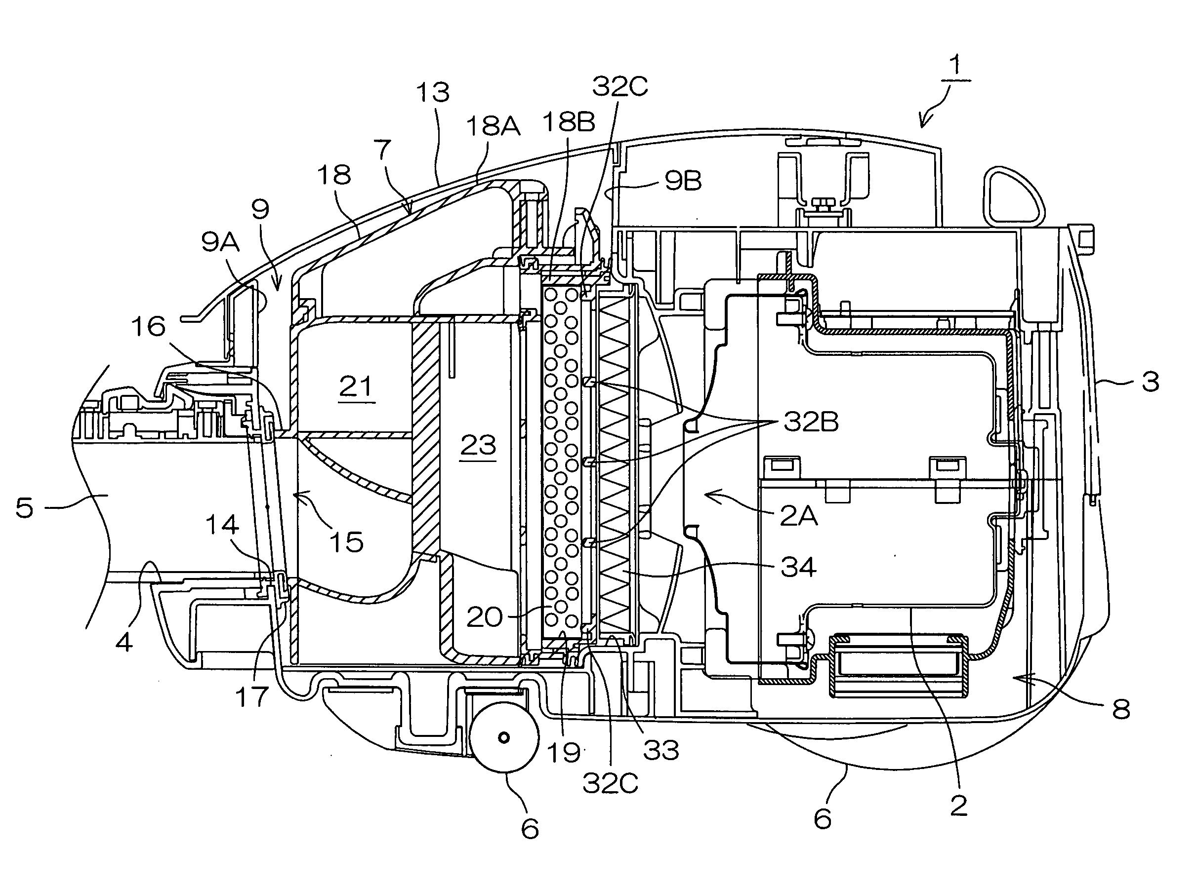
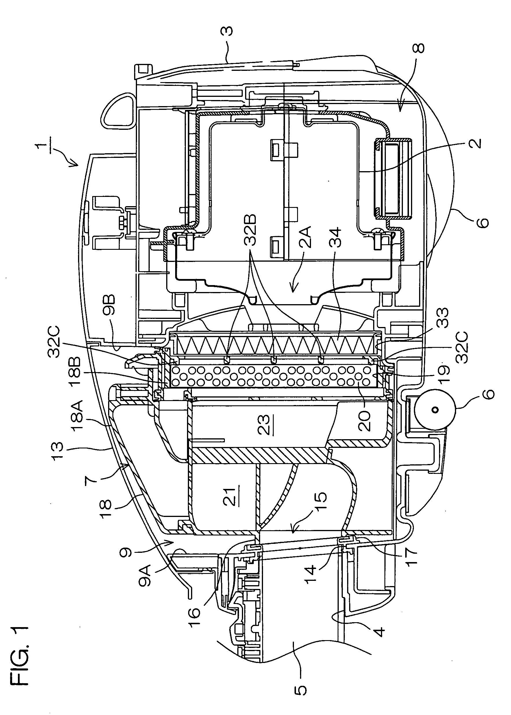
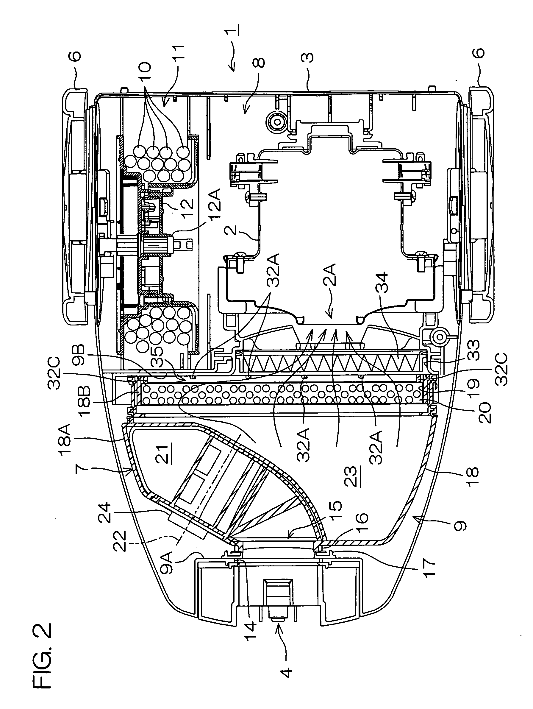
[0046]FIG. 1 is a sectional view of an electric vacuum cleaner 1 according to the present invention, the sectional view being taken along an anteroposterior vertical plane and seen from a right side. FIG. 2 is a sectional view of the electric vacuum cleaner 1 taken along a horizontal plane and seen from an upper side. A left side and a right side in FIG. 1 are respectively defined as a front side and a rear side of the electric vacuum cleaner 1. An upper side and a lower side in FIG. 2 are respectively defined as a left side and a right side of the electric vacuum cleaner 1.

[0047] Referring to FIGS. 1 and 2, the electric vacuum cleaner 1 includes a main body 3 having an electric fan 2, and a connection hose 5 having one end inserted into a suction port 4 provided at a front end of the main body 3 (in FIG. 2, the connection hose 5 is not shown). The connection hose 5 is an elongated tubular member with at least a part thereof having a bellows shape. Though not shown, a suction member...

second embodiment

[0066] The construction of the dust collecting apparatus 7 is not limited to the construction described above, but the dust collecting apparatus 7 may have the same construction as a dust collecting apparatus 107 to be described in detail with reference to FIGS. 8 to 10.

[0067]FIG. 5 is a sectional view of an electric vacuum cleaner 101 according to the second embodiment of the present invention, the sectional view being taken along an anteroposterior vertical plane and seen from a right side. FIG. 6 is a plan view of the electric vacuum cleaner 101 with its dust cover 113 removed. A left side and a right side in FIG. 5 are respectively defined as a front side and a rear side of the electric vacuum cleaner 101. An upper side and a lower side in FIG. 6 are respectively defined as a left side and a right side of the electric vacuum cleaner 101.

[0068] Referring to FIGS. 5 and 6, the electric vacuum cleaner 101 includes a main body 103 having an electric fan 102, and one end of a conne...


PUM


Abstract

In an inventive electric vacuum cleaner, a filter 20 through which air discharged from an air outlet port 19 is passed is provided on a rear face of a casing 18 of a cyclonic dust collecting apparatus 7, and held by a filter holder 18B. A rear face of the filter 20 is spaced from vertical ribs 32A of the filter holder 18B to define a guide passage 35 for guiding air discharged from a portion of the air outlet port 19 not opposed to an opening 33 through the filter 20 toward the opening 33. The guide passage 35 allows the air to pass through the portion of the air outlet port 19 not opposed to the opening 33.

Description

BACKGROUND OF THE INVENTION [0001] 1. Field of the Invention [0002] The present invention relates to an electric vacuum cleaner and a cyclonic dust collecting apparatus to be mounted in the electric vacuum cleaner. [0003] 2. Description of the Related Art [0004] Electric vacuum cleaners include, for example, a main body having an electric fan, a suction member to be moved along a floor surface, and a connection hose which connects the suction member to the main body, and a disposable filter bag is mounted in the main body. When an electric vacuum cleaner of this type is driven, outside air (air on the floor surface) is sucked from the suction member by driving the electric fan provided in the main body, and taken into the main body from a suction port of the main body through the connection hose. An inlet of the disposable filter provided in the main body communicates with the suction port. When the air sucked from the suction port passes through the disposable filter, dust entraine...

Claims


Application Information

Patent Timeline
Patent Type & Authority Applications(United States)
IPC IPC(8): A47L9/16
CPCA47L9/122A47L9/1427A47L9/1472A47L9/165A47L9/1666A47L9/1691A47L9/20
Inventor MATSUHASHI, HIROMICHIFUJIYOSHI, TOSHIYUKITSUCHIDA, HIDEYATAKAI, KEIUSHIO, SHOZO
Owner SANYO ELECTRIC CO LTD
Why Eureka
Try Eureka