Sliding assisting apparatus

a technology of sliding assist and sliding device, which is applied in the direction of building braking device, door/window fitting, construction, etc., can solve the problems of inconvenient use, lack of overall quality and functionality of the device, and user fatigue, and achieve excellent building-in characteristics and maintenance characteristics, and not limit the setup space of the devi

Inactive Publication Date: 2006-01-26
NIFCO INC
View PDF14 Cites 32 Cited by
  • Summary
  • Abstract
  • Description
  • Claims
  • Application Information

AI Technical Summary

Benefits of technology

[0014] The disclosed embodiments of the present invention offer numerous advantages. The above noted structure permits sliding between a midcourse position and a fully drawn-out position, or between a midcourse position and a fully drawn-in position, automatically by the force of the spring member, offering tremendous improvement from the viewpoint of convenience and ease of use. Also, because both assisting functions for the sliding operations, namely in both the drawing-in and drawing out directions can be achieved by a single unit construction, it has the advantage of providing excellent building-in characteristics and maintenance characteristics, tending not to limit the device setup space.

Problems solved by technology

H5-023763, in a structure in which a movable body is switched to slide between a drawn-in position and a drawn-out position on a base, it may be tiresome for the user and lack device overall quality and functionality if all the switching operations for sliding in the drawing-in direction and sliding in the drawing-out direction are performed by hand.
In the above-mentioned conventional structure, for example, although the movable body is slid automatically almost entirely from the drawn-out position to the drawn-in position, a strong pulling operation force by this amount is required in going from the drawn-in position to the drawn-out position, making it inconvenient for the user.
This causes a poor coupling force and the potential that the lock may be released due to vibrations, and the like.
Also, the conventional structure is limited in the operational characteristics in that it does not have functions for assisting both operations of the case when sliding the movable body in the direction of the drawn-in position and when sliding it in the direction of the drawn-out position.

Method used


Image

  • Sliding assisting apparatus
  • Sliding assisting apparatus
  • Sliding assisting apparatus

Examples


case 10c

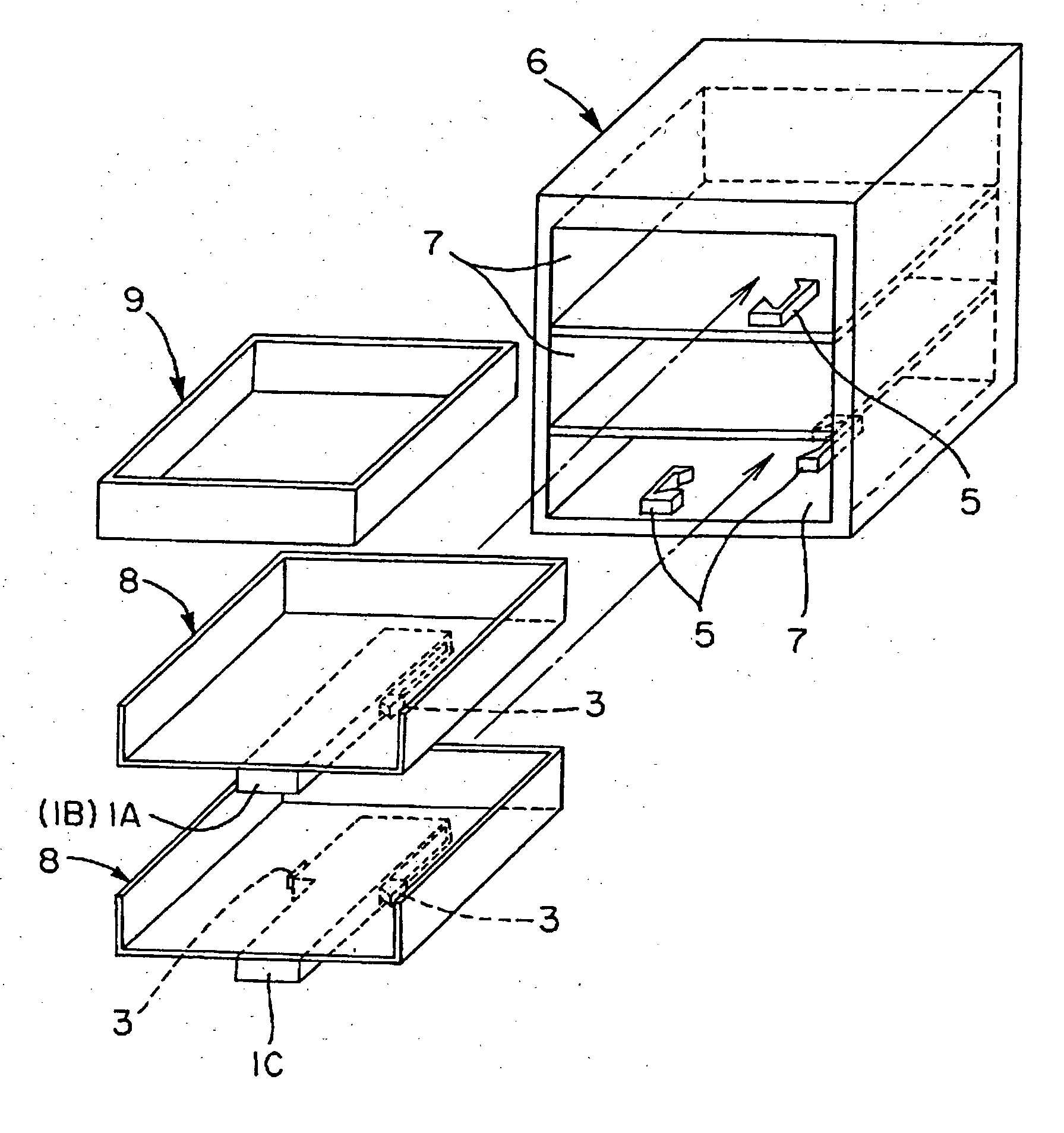
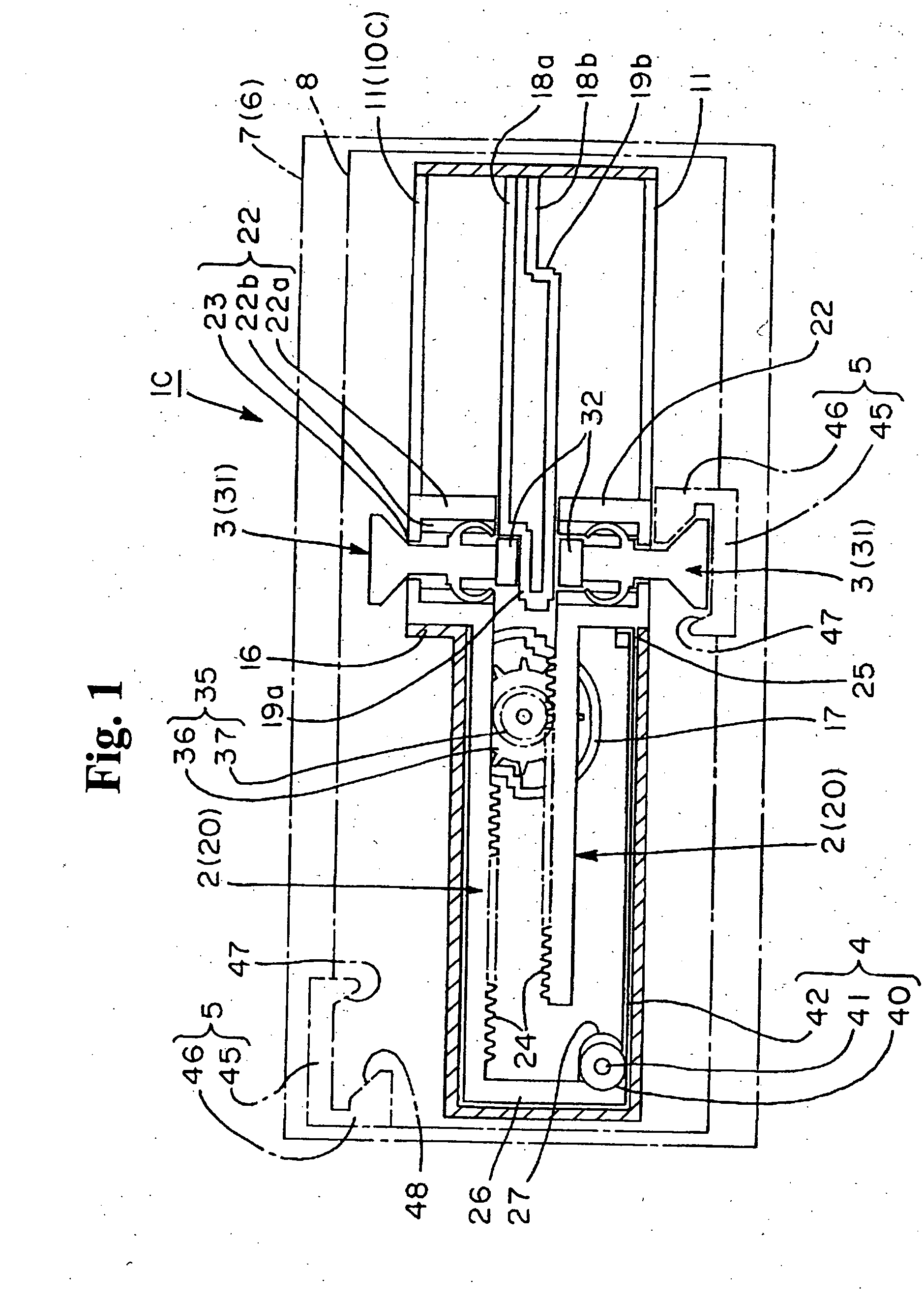
[0033] Case 10C has a rectangular container shape which is long in the sliding direction of the movable body 8 and is flat as depicted in FIG. 1. On one side wall of case 10C, of the two side walls shown facing oppositely in the lengthwise direction, the side back from approximately the middle front to the back sticks out by an amount corresponding to a vertical wall 16. Also, on both side walls, a long groove 11 is formed from about the middle position in the front-to-back direction to the back end as shown in FIG. 1.

[0034] On the inside bottom surface, the device has a roughly circular dividing rib 17 for damper placement in approximately its middle front to its back, and front-to-back ribs 18a, 18b which extend from the back side to near approximately the middle position between the front and back. A damper 35 is placed inside the dividing rib 17. The dividing rib 17 forms a damper receiving part, with one part serving as a step part. This damper receiving part functions as in th...


PUM


Abstract

A sliding assisting apparatus for assisting a sliding operation wherein a movable body slidably engaged with a base is slid between a first sliding position and a second sliding position includes sliders, a spring member, lock members and operation members. The sliders are engaged with the movable body and capable of sliding in the same one or more directions as the movable body. The spring member is capable of accumulating force in the sliding operation of the movable body and connecting the respective sliders together. The lock members are each capable of engaging with one of the sliders to exert the accumulated force on the slider, and disengaging from the slider to release the accumulated force from the slider. Operation members are each capable of engaging and disengaging with the lock member for engaging the lock member with a slider and disengaging a lock member from the slider.

Description

BACKGROUND OF THE INVENTION AND RELATED ARTS STATEMENT [0001] The present invention relates to a sliding assisting apparatus for assisting the sliding operation of a movable body, for example, such as a drawer in either direction between a drawn-in position and a drawn-out position on a base. [0002] As exemplified in Japanese Examined Patent No. H5-023763, in a structure in which a movable body is switched to slide between a drawn-in position and a drawn-out position on a base, it may be tiresome for the user and lack device overall quality and functionality if all the switching operations for sliding in the drawing-in direction and sliding in the drawing-out direction are performed by hand. In the JP H5-023763 reference, to overcome a design such that the movable body is forced in either direction of the drawn-out position or the drawn-in position, the device may be slid automatically toward a forced direction. [0003] FIGS. 10(a) and 10(b) respectively show the apparatus for a draw...

Claims


Application Information

Patent Timeline
Patent Type & Authority Applications(United States)
IPC IPC(8): A47B88/00A47B88/04E05F3/16E05F3/22E05F5/02E05F5/06
CPCA47B88/0477A47B88/047A47B88/463A47B88/467
Inventor SATO, HIROJIKOBAYASHI, YASUTOMOTSUCHIYA, TAKEFUMI
Owner NIFCO INC
Why Eureka
Try Eureka