
High-efficiency easy-cleaning sullage heat exchanger

An easy-to-clean, heat-exchanger technology, which is applied in the types of heat exchangers, indirect heat exchangers, lighting and heating equipment, etc., can solve the problems of heavy cleaning workload, high investment and maintenance costs, and achieve faster technological progress and better Excellent heat exchange effect and application effect

Active Publication Date: 2010-09-15
HEFEI GENERAL ENVIRONMENT CONTROL TECH
View PDF0 Cites 0 Cited by
  • Summary
  • Abstract
  • Description
  • Claims
  • Application Information

AI Technical Summary

Problems solved by technology

[0006] In order to solve the problems of the above two heat exchange forms, that is, the high initial investment and maintenance costs of the centralized heat exchanger and the large cleaning workload in the sewage immersion heat exchange form, the present invention provides an efficient and easy-to-clean sewage heat exchanger that is convenient for cleaning

Method used


Image

  • High-efficiency easy-cleaning sullage heat exchanger
  • High-efficiency easy-cleaning sullage heat exchanger
  • High-efficiency easy-cleaning sullage heat exchanger

Examples


Embodiment 1

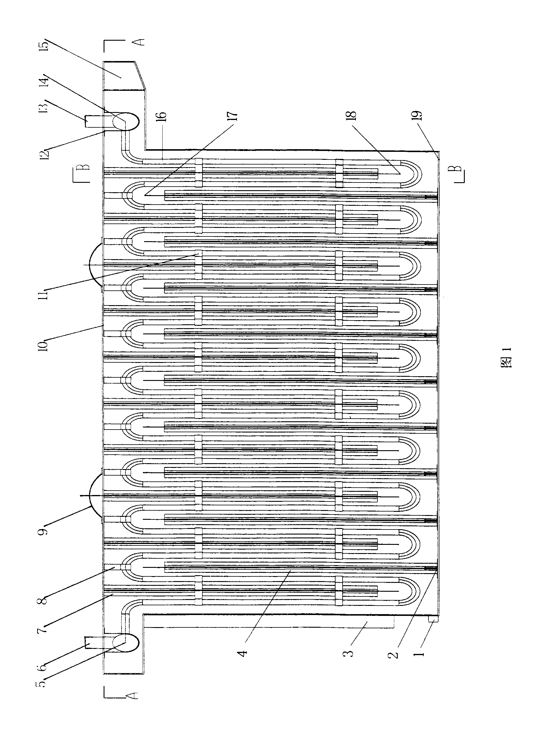
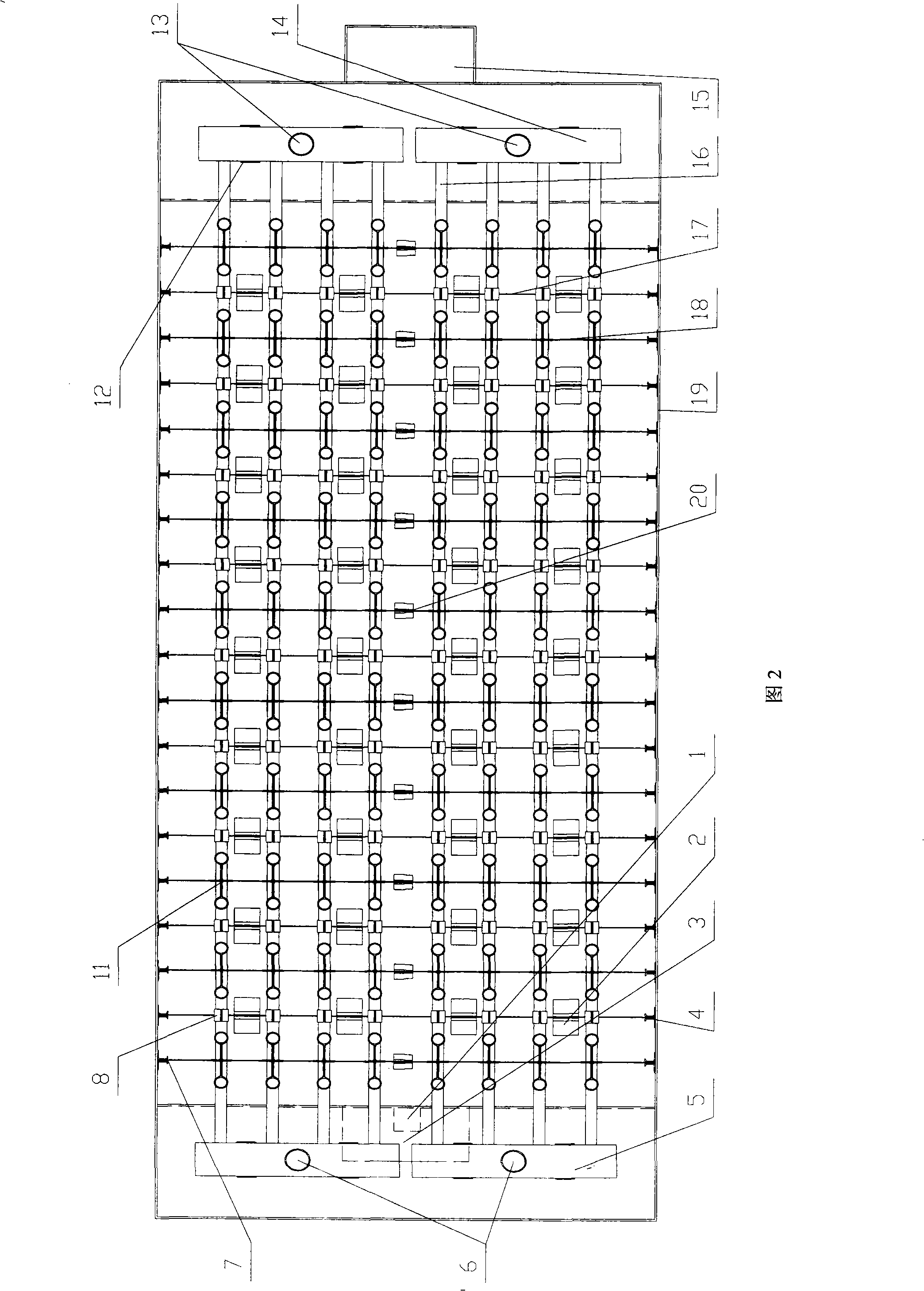
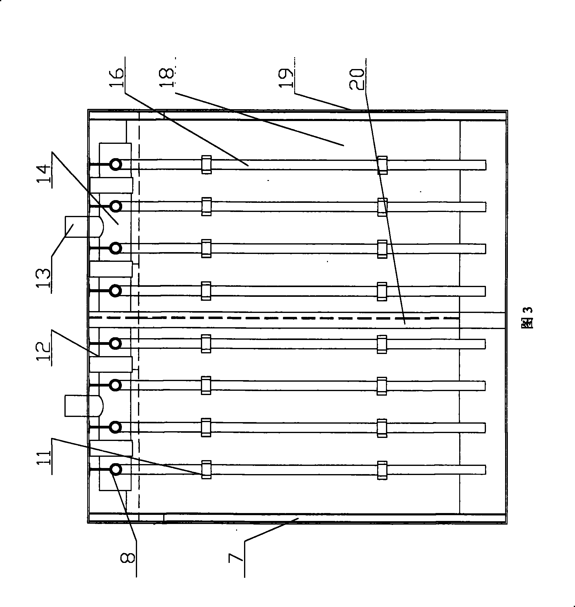
[0031] see figure 1 , figure 2 with image 3 , an efficient and easy-to-clean sewage heat exchanger includes a sewage tank 19, the top of the sewage tank 19 is provided with a flat upper top plate 10, and the inner surface of the upper top plate 10 is evenly equipped with upper baffles 18;

[0032] Four serpentine heat exchange tubes 16 are evenly distributed in the sewage tank 19, and each bend on the upper part of the serpentine heat exchange tubes 16 is connected to the inner side of the upper top plate 10 through fastening hangers 8, and the adjacent serpentine heat exchange tubes The distance between the tubes 16 in the horizontal direction should be large enough to ensure that they can be cleaned manually with a brush, and the distance should be at least greater than 50mm; one end of the serpentine heat exchange tube 16 is connected to the liquid distribution pipe 5, and the other end is connected to the liquid collection pipe 14 ;

[0033] The dispensing pipe 5 is ...

Embodiment 2

[0046] Consider the maintenance and cleaning of the heat exchanger. The upper top plate can be divided into 10 blocks, and one heat exchange tube can be divided into one piece, or two, three, four, etc., and different designs can be carried out according to different situations. figure 2 In the middle, 4 heat exchange tubes are used as a whole, and the whole heat exchanger has a total of 8 heat exchange tubes. Therefore, the upper top plate 10 is divided into two pieces. When cleaning, it can be taken out of the box one by one, rinsed with water or with a brush. Clean up.

[0047] Others are with embodiment 1.


PUM


Abstract

The invention relates to a multipurpose use device for low grade energy, namely, a high-efficiency cleaning sewage heat exchanger. The device comprises a sewage box body, the top of which is provided with a flat-shaped top plate. The sewage box body is internally distributed with more than two snakelike heat exchange tubes evenly. The upper part of the snakelike heat exchange tubes is connected with the inner side surface of the top plate. The inner bottom of the sewage box body is evenly distributed with a lower transverse baffle, the upper part of which extends into the convex position of the snakelike heat exchange pipe. The inner side surface of the top plate is evenly distributed with an upper transverse baffle, the lower part of which extends into a concave downward position of the snakelike heat exchange pipe. The upper part of the sewage box body is provided with a sewage inlet defrosting pan, the lower part is provided with a sewage outlet and the bottom is provided with a water outlet. Compared with the traditional shell and tube exchanger, the device ensures higher heat exchange efficiency based on reducing the treatment cost of sewage of the heat exchanger, heat transfer coefficient of which can reach more than 400 W / m<2>.k, and also ensures that the heat exchanger has better maintenance characteristics, thus being convenient for daily maintenance and cleaning and keeps better heat exchange efficiency.

Description

technical field [0001] The invention relates to a comprehensive utilization device of low-grade energy, specifically a high-efficiency and easy-to-clean sewage heat exchanger. Background technique [0002] For the comprehensive utilization and reuse of low-grade energy, it is an extremely effective energy-saving measure in the current society where energy issues are increasingly tense. In the refrigeration and air conditioning heat pump industry, the utilization of low-grade energy is quite extensive. Both industrial sewage and domestic sewage are low-grade energy sources. The recovery and reuse of this low-grade energy is mainly through heat exchangers to transfer and transfer heat from waste water and hot water. [0003] The system forms of using sewage as heat exchange for air-conditioning systems are also gradually increasing in China. The main form is the system form of centralized heat exchange, that is, after the sewage is briefly treated, it is sent to the central h...

Claims


Application Information

Patent Timeline
Patent Type & Authority Patents(China)
IPC IPC(8): F28D7/08
Inventor 田旭东张秀平岳海兵钟瑜贾磊周到王磊
Owner HEFEI GENERAL ENVIRONMENT CONTROL TECH
Learn More