Phase control switching device

a switching device and phase control technology, applied in circuit arrangements, emergency protective circuit arrangements, electrical equipment, etc., can solve the problem that the incoming current caused by the switching device which is severe to a transformer cannot be suppressed to the minimum level, and achieve the effect of reducing the number of transformers

Active Publication Date: 2006-01-26
MITSUBISHI ELECTRIC CORP
View PDF6 Cites 13 Cited by
  • Summary
  • Abstract
  • Description
  • Claims
  • Application Information

AI Technical Summary

Benefits of technology

[0009] According to the phase control switching device of the present invention, each contact terminal of each breaker is opened at the voltage zero point of any one phase of three phases or a set specific phase at the same time with respect to the three phases, and the phase opened at the voltage zero point is set as a first throwing phase. When current is broken for the three phases simultaneously with the opening of the respective breakers of the three phases, the residual magnetic flux level of each phase of the transforming unit can be controlled so that the residual magnetic flux level of the phase broken at the voltage zero point is maximum (for example, −2 K or +2 K) while the residual magnetic flux levels of the other two phases are set to be opposite in polarity to the residual magnetic flux level of the phase concerned and equal to substantially the same residual magnetic flux level (for example, +K and +K or −K and −K) which is equal to about a half of the residual magnetic flux level of the phase concerned. Therefore, by first throwing the phase broken at the voltage zero point, the difference in residual magnetic flux between the second throwing phase and the third throwing phase just before the first phase is thrown can be made substantially equal to zero. Accordingly, since the second throwing phase and the third throwing phase can be thrown at the electrical degree at which the residual magnetic flux and the stationary magnetic flux thereof are substantially coincident with each other, occurrence of the transitional phenomenon of the magnetic flux can be suppressed, and occurrence of magnetic saturation can be suppressed because the magnetic flux becomes symmetrical magnetic flux, so that the transitional exciting incoming current caused by the switching of the switching device which is severe to the transforming unit can be suppressed to the minimum level.

Problems solved by technology

Accordingly, there is a drawback that transitional exciting incoming current caused by switching of the switching device which is severe to a transformer cannot be suppressed to the minimum level when magnetic saturation occurs.

Method used


Image

  • Phase control switching device
  • Phase control switching device
  • Phase control switching device

Examples


first embodiment

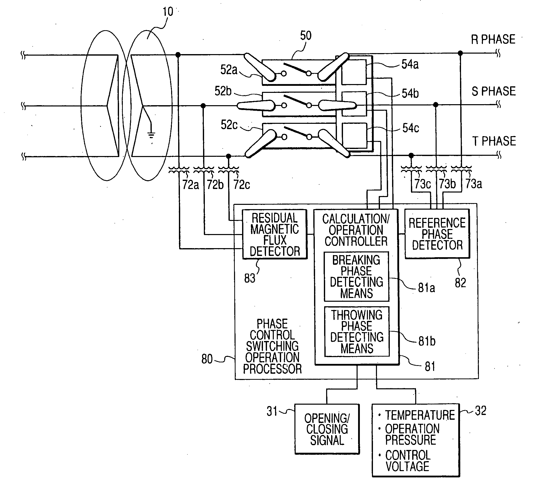
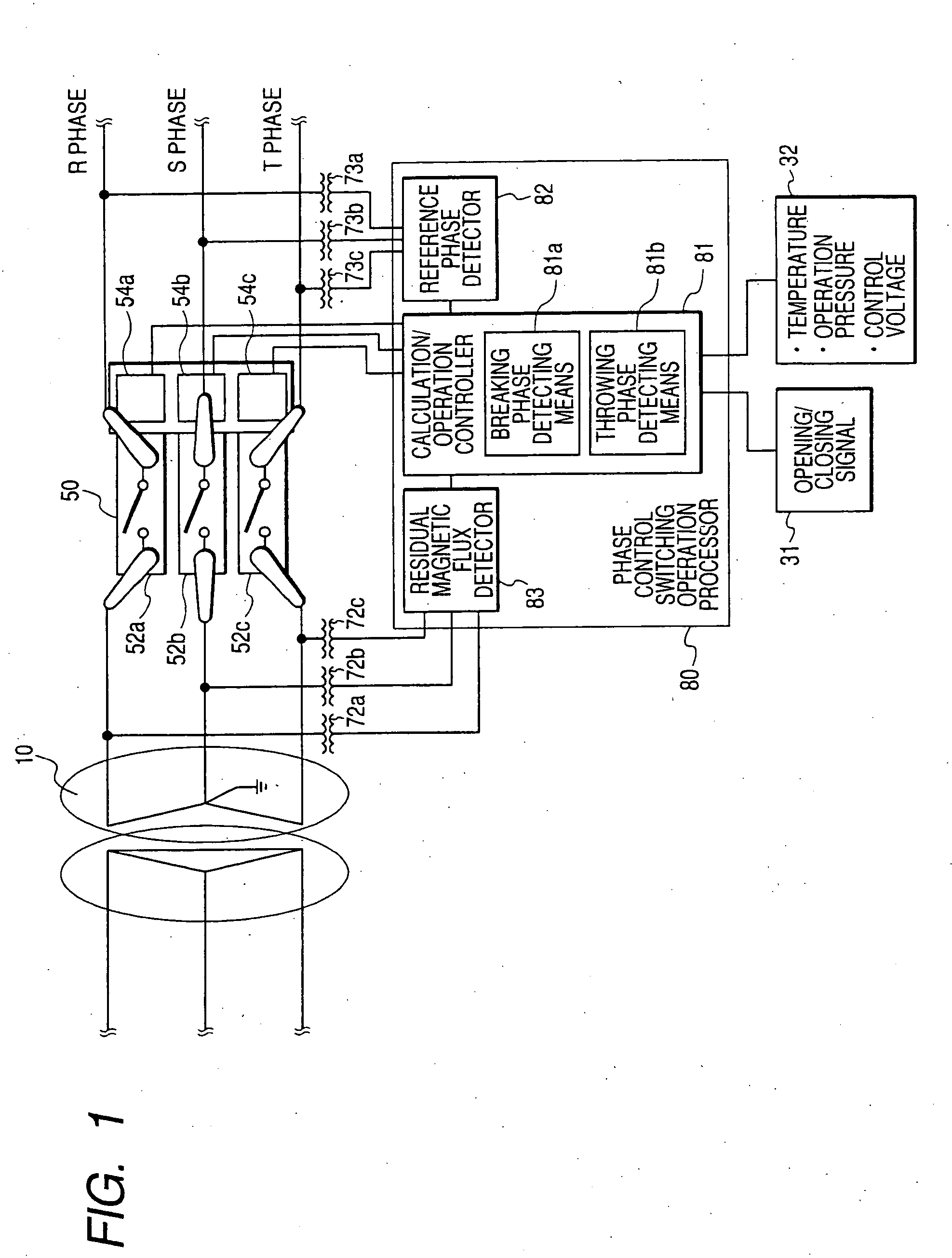
[0016]FIG. 1 is a block diagram showing the construction of a phase control switching device according to a first embodiment of the present invention. In FIG. 1, reference numeral 10 represents a transforming unit such as a transformer or a shunt reactor, and it is representatively indicated by a transformer 10. The transformer 10 is connected to a power system of an electric feeder line through a breaker 50. In order to allow contact terminals in arc-suppressing rooms 52a, 52b, 52c of the breaker 50 to independently carry out a switching (opening / closing) operation, independent operating devices 54a, 54b, 54c are provided. Voltage measuring units 72a, 72b, 72c and 73a, 73b, 73c are respectively provided between the transformer 10 of each R, S, T phase and the breaker 50 and at the power system side of the breaker 50 of each R, S, T phase. A phase control switching operation processor 80 comprises a computer or the like, and contains a reference phase detector 82, a calculation / oper...

second embodiment

[0031] In the first embodiment, the voltage measuring unit for measuring the voltages at the transforming unit side of the breaker and the power system side is equipped with a breaker of each phase. If the phase control switching operation processor is equipped with a function of setting any specific phase of the three phases when the breaker of each phase receives an opening instruction, the voltage measuring unit for measuring the voltages at the transforming unit side of the breaker and the power system side may be equipped to the breaker for the specific phase.

[0032] As described above, the phase control switching device is equipped with the transforming unit connected to the power system, the breaker, which is connected to the transforming unit, of each phase which is thrown to break failure current or load current of the transforming unit and excites the transforming unit, a voltage measuring unit for measuring the voltages at the transforming unit and the power system side o...


PUM


Abstract

Respective contact terminals in respective arc-suppressing spaces of respective breakers are opened at a voltage zero point of any phase of three phases, simultaneously among the three phases. If current breaking is carried out for the three phases at the same time, when the breakers of the three phases are opened, the residual magnetic levels of the respective phases of a transformer can be controlled so that the residual magnetic flux level of the phase opened at the voltage zero point is maximum (for example, −2 K or +2 K) and the residual magnetic flux level of the other two phases are opposite in polarity to the residual magnetic flux level of the phase concerned and equal to substantially the same residual magnetic flux (for example, +K and +K or −K and −K) which is equal to about one half of the residual magnetic flux level of the phase concerned. Accordingly, by throwing the phase broken at the voltage zero point at a first time, the difference in residual magnetic flux between the second throwing phase and the third throwing phase just after the first phase is thrown can be substantially nullified.

Description

BACKGROUND OF THE INVENTION [0001] 1. Field of the Invention [0002] The present invention relates to a phase control switching device for controlling an switch time of an switching device for power such as a breaker in consideration of residual magnetic flux of the core of a transformation device of electrical energy such as a transformer or a shunt reactor, whereby occurrence of transitional exciting incoming current caused by switching of the switching device which is severe to the transformation device connected to a power system can be suppressed to the minimum level. [0003] 2. Description of the Related Art [0004] There is known a phase control switching device in which when residual magnetic flux exists in the core of a transformer or the core of a shunt reactor, a transitional switch surge phenomenon is suppressed by estimating the residual magnetic flux of each phase of the transformer or shunt reactor and operating a breaker at the optimal throw-in timing corresponding to t...

Claims


Application Information

Patent Timeline
Patent Type & Authority Applications(United States)
IPC IPC(8): H02H3/18H02H3/26
CPCH02H7/04H02H3/021
Inventor KINOSHITA, SADAYUKIITO, HIROKIKOHYAMA, HARUHIKOKAMEI, KENJI
Owner MITSUBISHI ELECTRIC CORP
Why Eureka
Try Eureka