

Optical apparatus
- Summary
- Abstract
- Description
- Claims
- Application Information
AI Technical Summary
Problems solved by technology
Method used
Image

Examples
Embodiment Construction
[0067] Embodiments of the invention will be described in detail by way of experimental results with reference to the drawings.
[0068] In this specification, the term multiple divided-domain Faraday rotator is used to cover a Faraday rotator that is made of a bismuth-substituted rare earth iron garnet single crystal film and is divided into multiple areas of a single domain structure when the Faraday rotator is in a plurality of external magnetic fields.
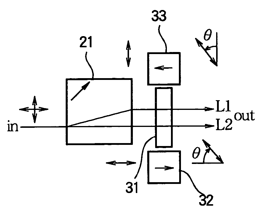
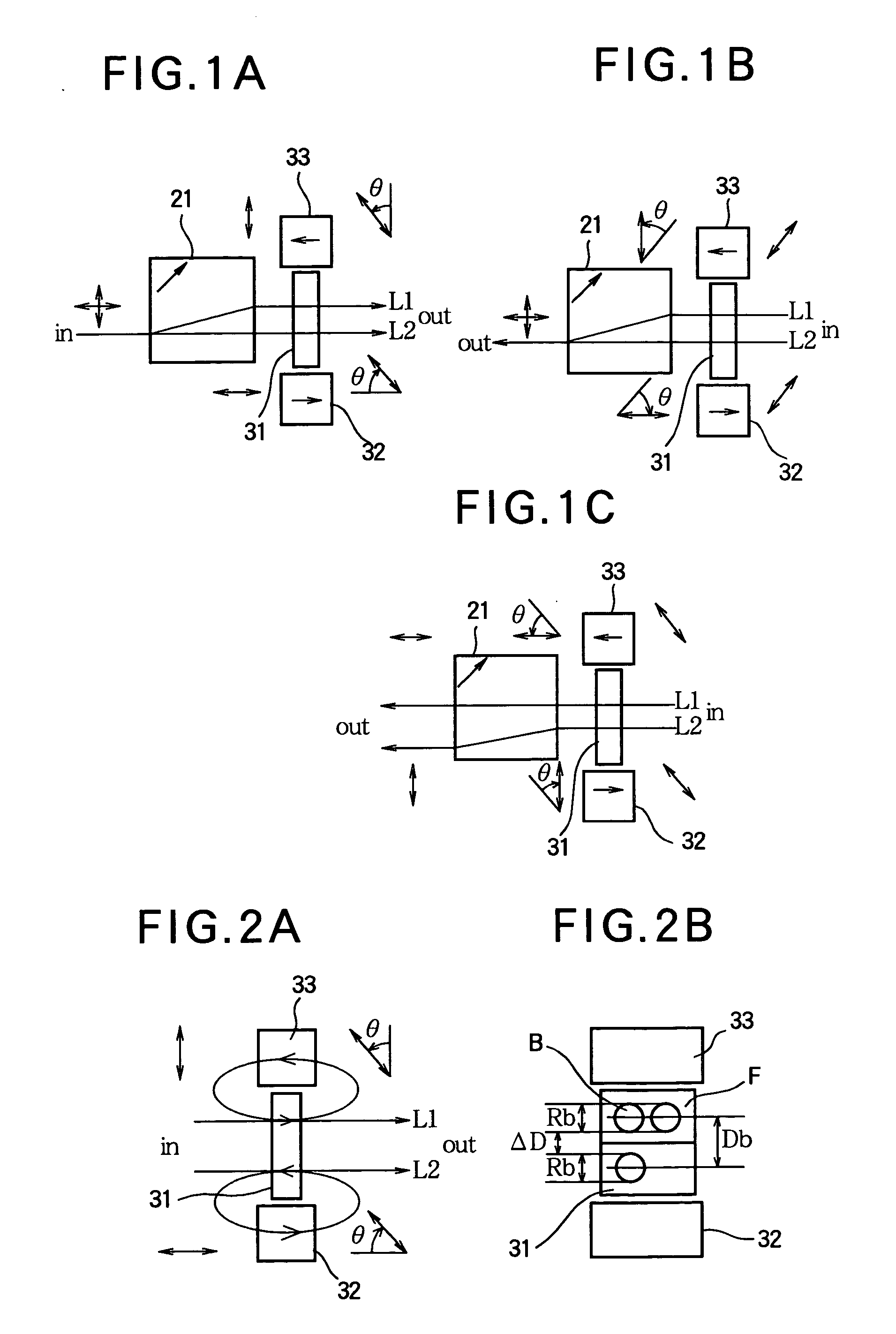
[0069] FIGS. 1A-1C illustrate the principle of operation of an optical apparatus that uses a Faraday rotator (referred to as a double divided-domain Faraday rotator) according to the invention.
[0070] The optical device according to the invention includes a Faraday rotator made of a bismuth substituted rare-earth iron garnet single crystal (BIG) 31 having a Faraday rotation of about 45 degrees, permanent magnets 32 and 33 arranged relative to the Faraday rotator, and a birefringent block 21. The magnetic fields of the permanent magnets ...
PUM
 Abstract
Description
Claims
Application Information