Coercivity performance determination device for coercivity distribution magnet

a coercivity and performance determination technology, applied in the direction of magnetic bodies, instruments, susceptibility measurements, etc., can solve the problems of time-consuming checking process and difficult determination of whether or not each part has the required coercivity, and achieve the effect of short time period and low cost of performance tes

Active Publication Date: 2013-06-06
TOYOTA JIDOSHA KK
View PDF0 Cites 5 Cited by
  • Summary
  • Abstract
  • Description
  • Claims
  • Application Information

AI Technical Summary

Benefits of technology

[0047]As can be understood from the description above, according to a coercivity performance determination device for a coercivity distribution magnet of the present invention, a reverse magnetic field corresponding to the coercivity required of each part of the coercivity distribution magnet is formed with an external magnetic field generated when magnetism caused by an excitation means flows through an external magnetic field generation mean

Problems solved by technology

However, since rare metals, such as dysprosium, terbium, etc., are used for these metal particles, one important problem to be solved in the art from the perspective of manufacturing cost reduction for permanent magnets is how to reduce the used amount thereof while

Method used


Image

  • Coercivity performance determination device for coercivity distribution magnet
  • Coercivity performance determination device for coercivity distribution magnet
  • Coercivity performance determination device for coercivity distribution magnet

Examples


Embodiment Construction

[0072]Embodiments of the present invention are described below with reference to the drawings. Although the protrusions are provided in the center regions of the end faces of the magnetic body in the illustrated examples, the configuration of the external magnetic field generation means is of course by no means limited to those of the illustrated examples, and, for example, in generating an external magnetic field forming a reverse magnetic field corresponding to the coercivity required of each part of a coercivity distribution magnet, protrusions may be provided at edge parts of the end faces, at regions closer to the edge parts, and so forth.

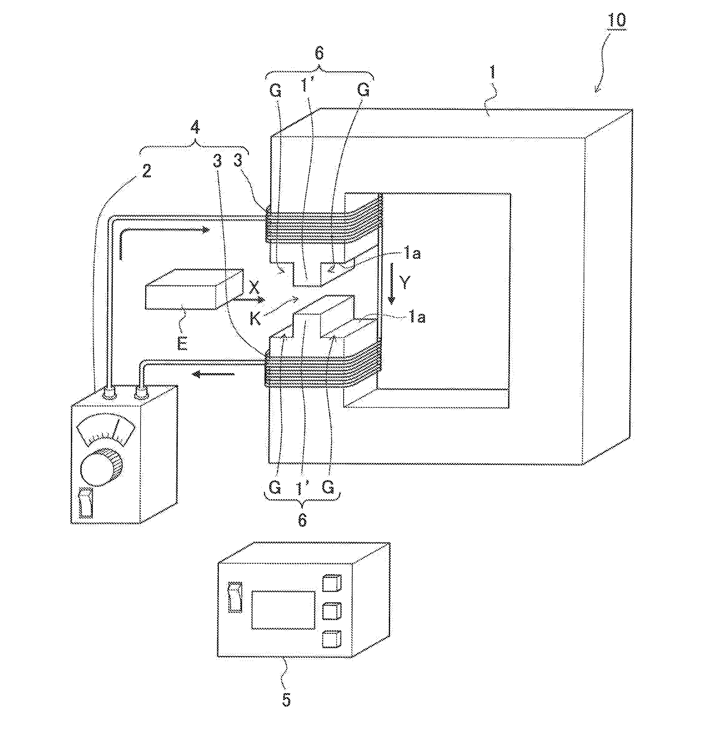
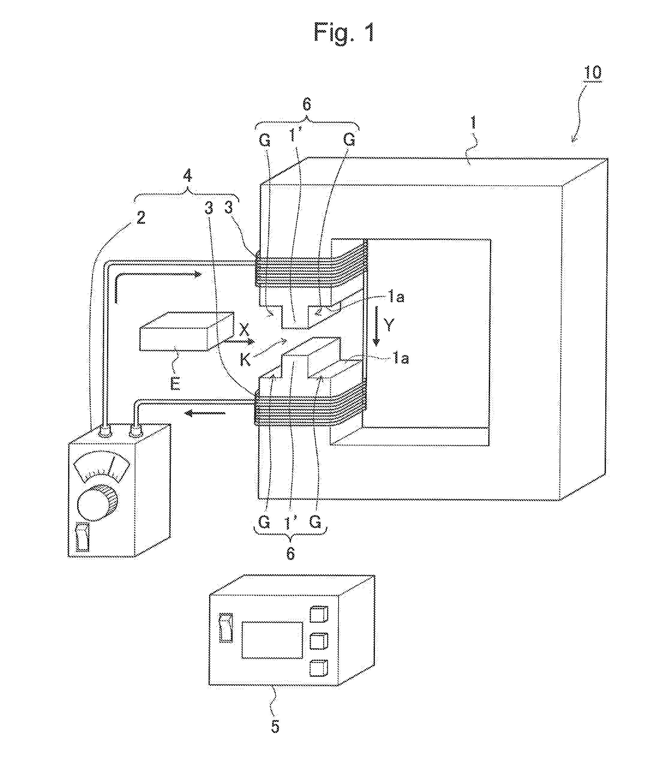
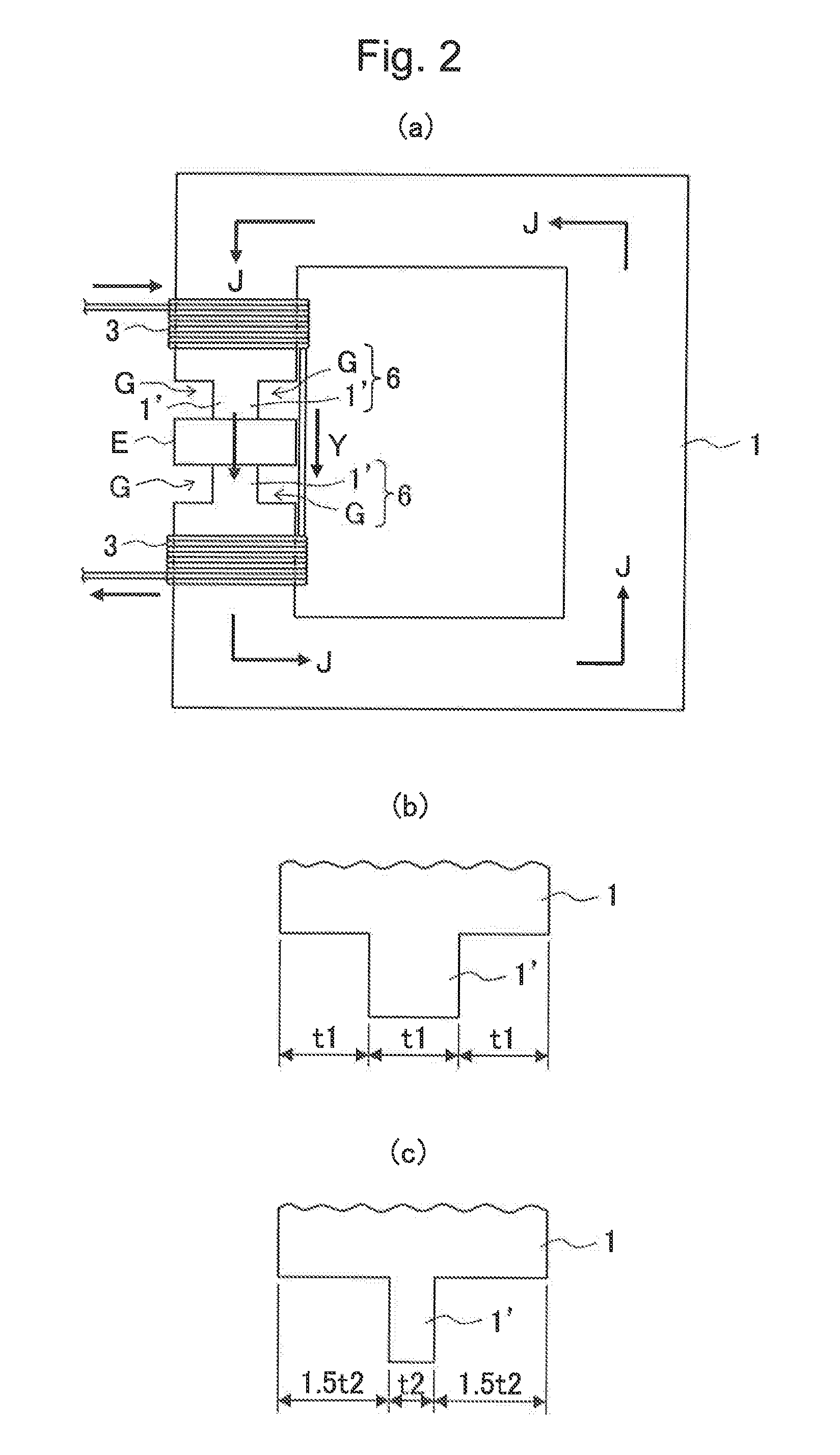
[0073]FIG. 1 schematically shows a coercivity performance determination device of the present invention which determines the coercivity performance of a coercivity distribution magnet. FIG. 2a is a diagram illustrating a state where a coercivity distribution magnet is placed in the coercivity performance determination device shown in FIG. 1 an...


PUM


Abstract

There is provided a coercivity performance determination device for a coercivity distribution magnet that is capable of determining, in a short period of time, with precision, and at as low a testing cost as possible, whether or not each part of one coercivity distribution magnet has a coercivity that is equal to or greater than the required coercivity. A coercivity determining device of the present invention comprises: a substantially C-shaped magnetic body; excitation means that generates a magnetic flow in the magnetic body; and a flux meter that measures the residual magnetic flux of the coercivity distribution magnet. Protrusions are provided at corresponding positions on two opposing end faces of the magnetic body, and the coercivity distribution magnet is held between the two protrusions to form an annular magnetic circuit. An external magnetic field generation means is formed by magnetic regions caused by the protrusions and non-magnetic regions comprising the air in the periphery thereof. An external magnetic field that is generated when magnetism flows through the protrusions is adjusted in such a manner that a reverse magnetic field, which comprises the sum of the external magnetic field and the demagnetizing field of the coercivity distribution magnet, corresponds to the coercivity required of each part of the coercivity distribution magnet. The residual magnetic flux when this has acted as the reverse magnetic field is measured with the flux meter to determine coercivity performance.

Description

TECHNICAL FIELD[0001]The preset invention relates to a coercivity performance determination device for a coercivity distribution magnet which determines whether or not each part of a coercivity distribution magnet for use in a motor has a coercivity that is equal to or greater than the required coercivity.BACKGROUND ART[0002]A permanent magnet embedded within a rotor of an IPM motor, etc., is required to have a coercivity that makes it possible to resist demagnetization caused by an external magnetic field coming from the stator core side.[0003]The external magnetic field acting on this permanent ma net is generally such that, with respect to a plan view of the rotor in which the permanent magnet is embedded, it is greatest at the corner parts on the stator core-side of the permanent magnet, while becoming smaller towards the center of the rotor core.[0004]On the other hand, with respect to sintered permanent magnets, metal particles for enhancing the coercivity performance of the p...

Claims


Application Information

Patent Timeline
IPC IPC(8): G01R33/16
CPCG01R33/16G01R33/123
Inventor SUZUKI, MASAFUMINAKANISHI, MAYUMI
Owner TOYOTA JIDOSHA KK
Why Eureka
Try Eureka