Controlled switching devices and method of using the same

一种受控开关、电气开关的技术,应用在电气工程领域

Active Publication Date: 2017-04-26
VIZIMAX
View PDF11 Cites 5 Cited by
  • Summary
  • Abstract
  • Description
  • Claims
  • Application Information

AI Technical Summary

Problems solved by technology

In addition, there is nothing to ensure that the intersection point of the steady-state magnetic flux and the residual magnetic flux of the phase with the smallest residual magnetic flux among the three phases is always within a specific area, as described in claim 1 of US Patent US8310106

Method used


Image

  • Controlled switching devices and method of using the same
  • Controlled switching devices and method of using the same
  • Controlled switching devices and method of using the same

Examples


Embodiment Construction

[0031] A new type of controlled switching device and its use method will be described below. Although the present invention is described and illustrated by specific examples, it should be understood that the embodiments described herein are for reference only, and the scope of application of the present invention is not limited thereto.

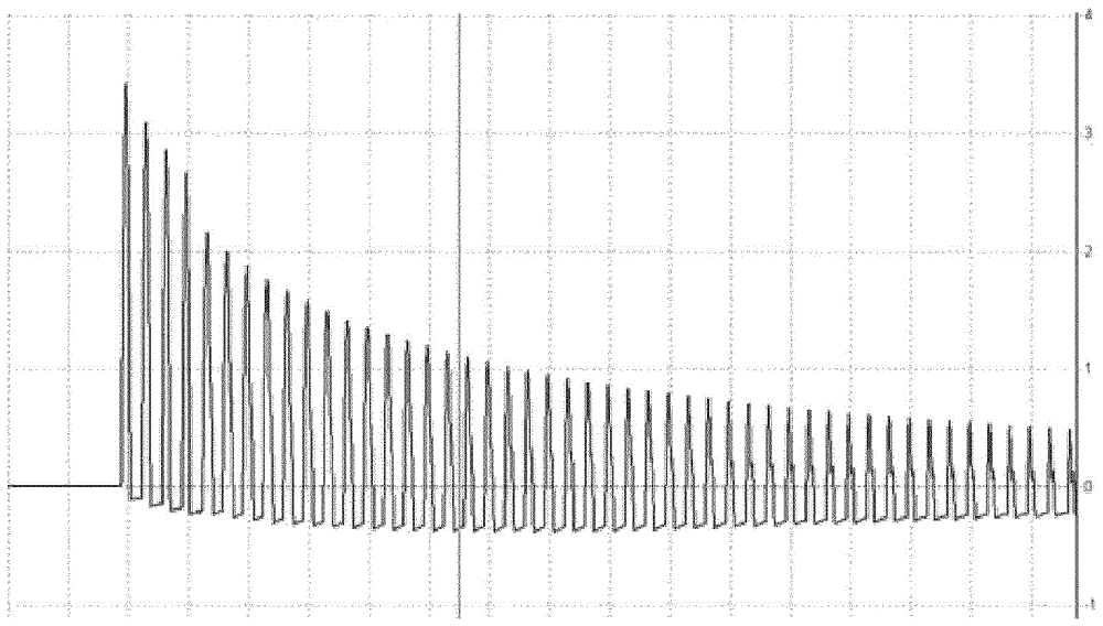
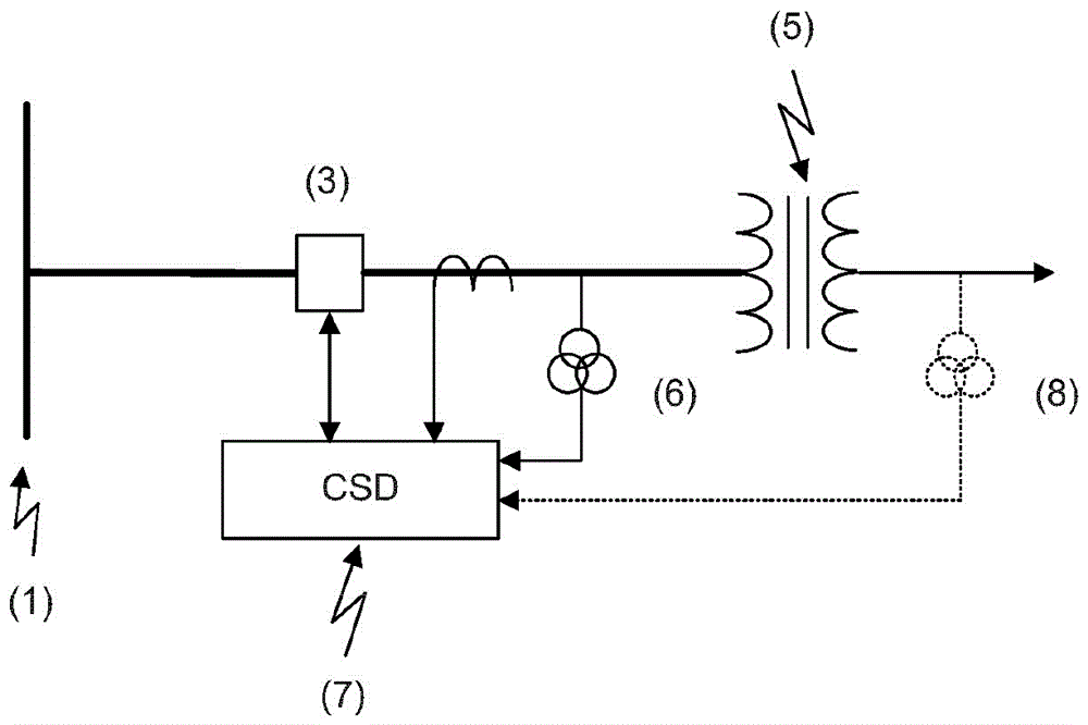
[0032] This invention relates to the use of CSD to control the action of the circuit breaker to switch the power transformer to reduce and (or) eliminate the inrush current. The CSD automatically determines the optimal electrical circuit breaker according to the size and polarity of the residual magnetic flux of the transformer core Switch angle. CSD evaluates the residual magnetic flux by mathematically integrating the voltage measured on the high-voltage side and the low-voltage side of the transformer when the transformer is powered off.

[0033] for figure 2 , Shows an example, the circuit is connected to the transformer (5), the transformer...


PUM


Abstract

This invention describes a method and an electrical circuit for controlling the closing of a three-phase circuit breaker with simultaneous pole operation to mitigate the inrush current resulting from power transformer energization by taking into account the residual magnetic flux in the transformer's magnetic core. It is disclosed a method to perform controlled switching on transformer and therefore mitigate the inrush current. It is disclosed that this method can be applied to any configuration of transformers which can be, but not limited to, Y-delta, Y-Y, delta-delta and delta-Y with either floating or grounded neutral.

Description

[0001] Related application [0002] The present invention claims the priority of US Provisional Application 62 / 020,037 "Controlled Switching Devices and Methods of Use" filed with the US Patent and Trademark Office on July 2, 2014, which is incorporated herein by reference. Technical field [0003] The present invention generally relates to the field of electrical engineering. The present invention particularly relates to a device and method for reducing the magnitude of inrush current generated when a power transformer controlled by a three-phase circuit breaker (CB) is energized. The three poles of the three-phase circuit breaker operate simultaneously, which is also called a three-pole linkage circuit breaker or Combination linkage circuit breaker. This patent can also be applied to a single-pole circuit breaker that operates independently, which can close all three electrodes at the same time. The invention also relates to controlled switch devices (CSDs) and methods of use. ...

Claims


Application Information

Patent Timeline
Patent Type & Authority Applications(China)
IPC IPC(8): H02H9/02H01F27/42H02H7/04
CPCH02H9/002H01F27/42H02H7/04
Inventor A·伊杰迪尔P·泰尔弗
Owner VIZIMAX
Why Eureka
Try Eureka