Fuel pressure controller

a technology of fuel pressure controller and controller, which is applied in the direction of electric control, fuel injecting pump, machine/engine, etc., can solve the problems of insufficient reduction of residual magnetic flux, and achieve the effect of reducing the number of operations, and prolonging the interval

Inactive Publication Date: 2008-09-30
DENSO CORP
View PDF11 Cites 6 Cited by
  • Summary
  • Abstract
  • Description
  • Claims
  • Application Information

AI Technical Summary

Benefits of technology

[0010]According to an aspect of the present invention, a fuel pressure controller has a reduction device that reduces the number of operations of a discharge metering valve to lengthen an interval between pressure-feeding operations with respect to the shortest cycle, in which a fuel pump can discharge fuel, when rotation speed of an internal combustion engine is equal to or higher than predetermined speed.
[0011]In this structure, the shortest cycle, in which the fuel pump can discharge the fuel, coincides with the operation cycle of the discharge metering valve during normal processing. The time interval between the operations of the discharge metering valve shortens as the rotation speed increases. Therefore, there is a possibility that the residual magnetic flux does not reduce sufficiently during the time interval. Moreover, the force applied to the discharge metering valve by the fuel increases and the spontaneous closure of the discharge metering valve is induced more as the rotation speed increases. The above-described structure reduces the number of the operations of the discharge metering valve to lengthen the interval between the pressure-feeding operations when the rotation speed is equal to or higher than the predetermined speed. Accordingly, the residual magnetic flux of the discharge metering valve can be suitably reduced. As a result, the rotation speed causing the spontaneous closure of the discharge metering valve can be increased, so the control of the fuel pressure can be suitably performed.

Problems solved by technology

Therefore, there is a possibility that the residual magnetic flux does not reduce sufficiently during the time interval.

Method used


Image

  • Fuel pressure controller
  • Fuel pressure controller
  • Fuel pressure controller

Examples


first embodiment

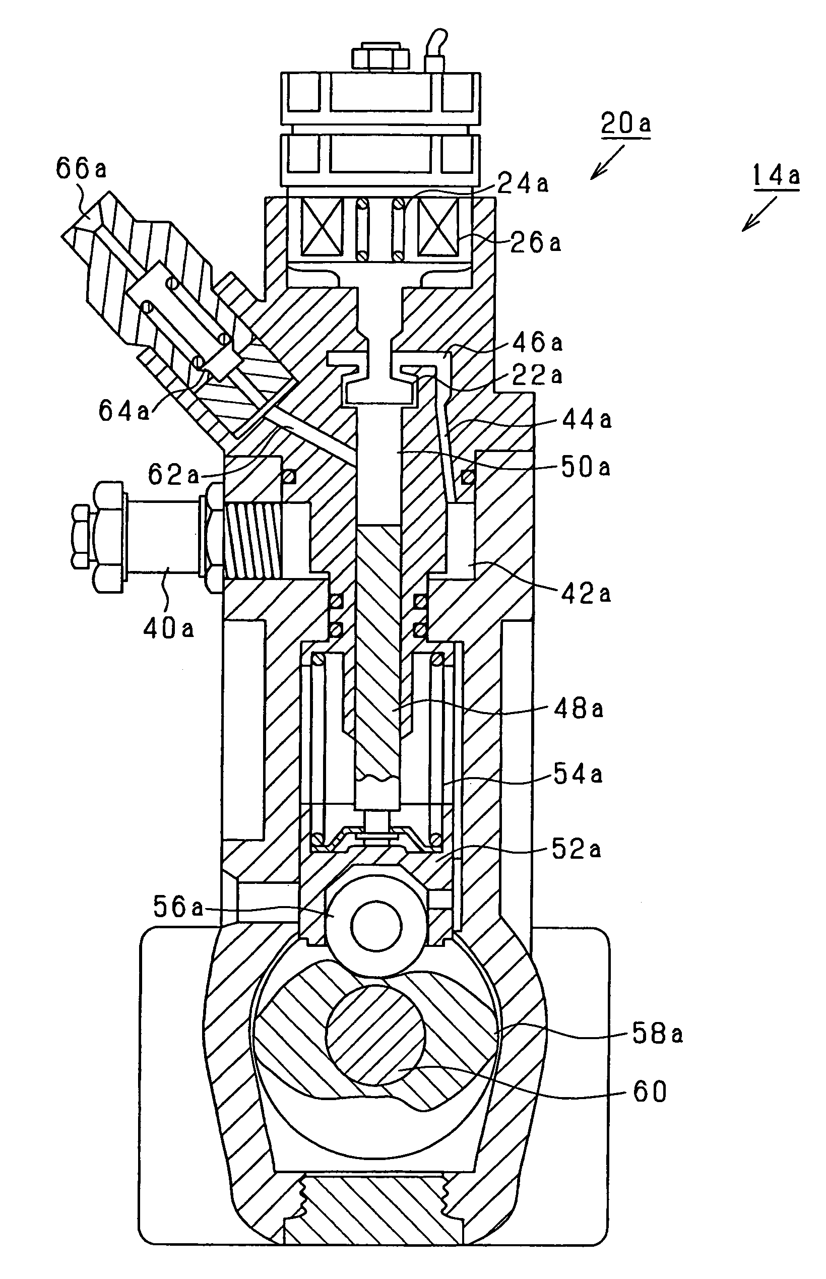
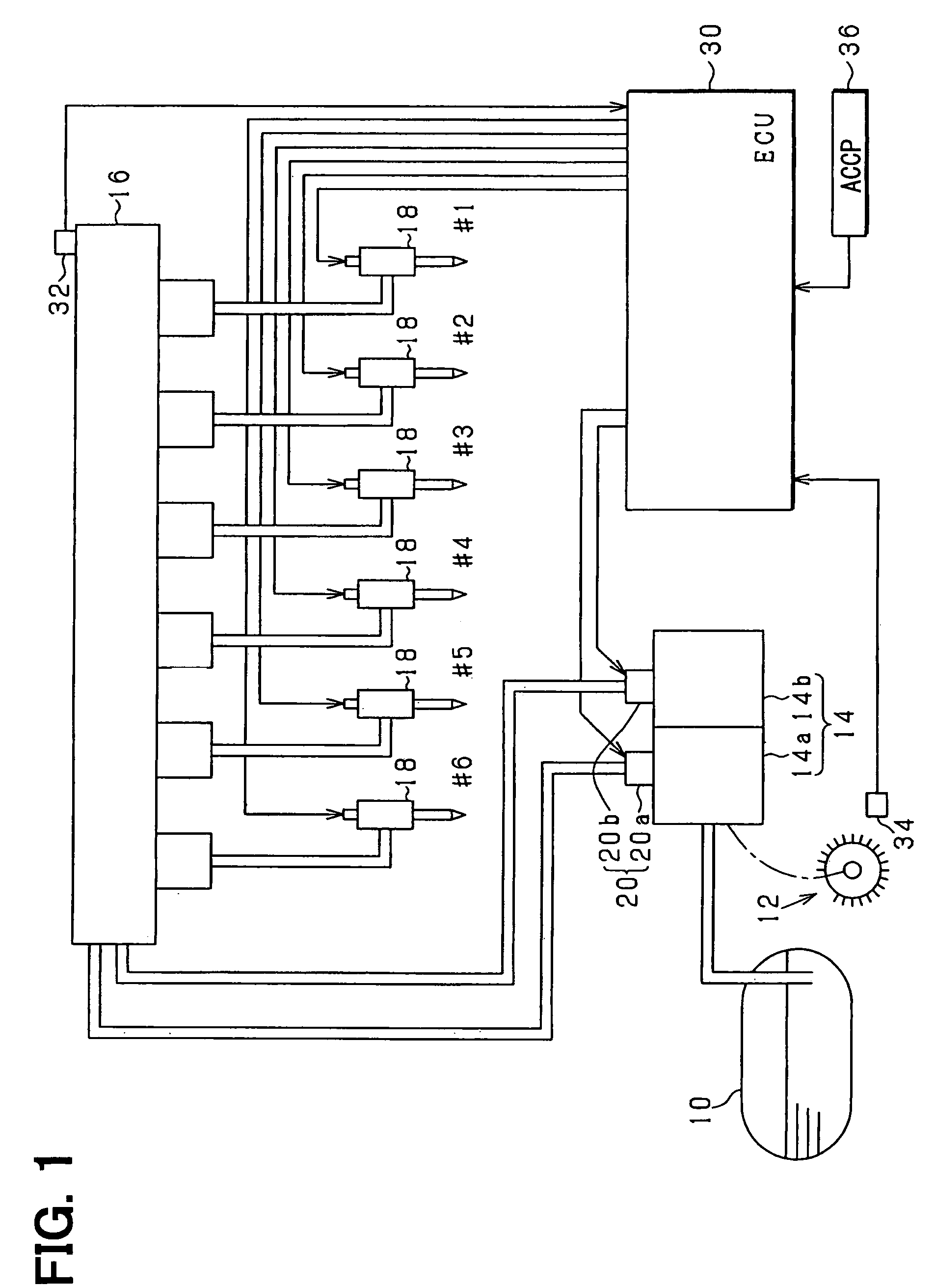
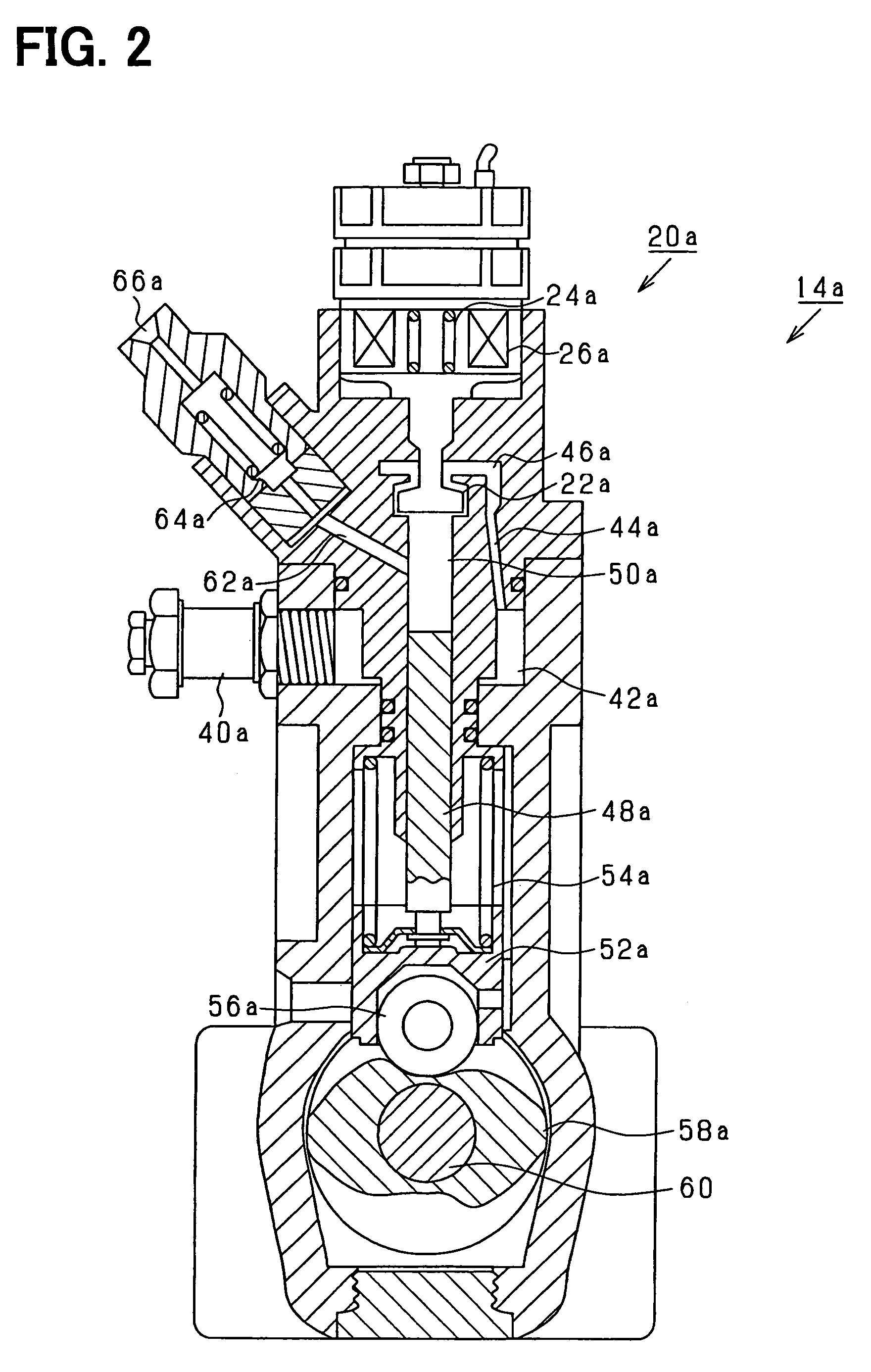
[0024]Referring to FIG. 1, an engine system according to the present invention is illustrated. An engine-driven fuel pump 14 draws fuel stored in a fuel tank 10. The fuel pump 14 is applied with a force by an output shaft 12 of a diesel engine. The fuel pump 14 includes a pair of fuel pumps 14a, 14b and a discharge metering valve 20 consisting of a pair of normally-open discharge metering valves 20a, 20b. The discharge metering valve 20 regulates a discharged fuel amount out of the fuel drawn from the fuel tank 10. The fuel discharged from the fuel pump 14 is pressure-fed to a common rail 16, which supplies the fuel to injectors 18 of respective cylinders (six cylinders in the present embodiment).

[0025]An electronic control unit 30 (ECU) receives sensing values of various sensors sensing operation states of the engine such as a fuel pressure sensor 32 sensing the fuel pressure in the common rail 16 and a rotation angle sensor 34 sensing a rotation angle of the output shaft 12 and a ...

second embodiment

[0058]Next, a system according to the present invention will be explained. FIGS. 10A and 10B show a switching mode among the normal processing, the reduction processing and the suction prohibiting processing according to the present embodiment. As shown in FIGS. 10A and 10B, in the present embodiment, a condition, under which the rotation speed NE of the output shaft 12 coincides with rotation speed α1, is used as a lengthening condition for switching from the normal processing to the reduction processing in accordance with the increase of the rotation speed NE of the output shaft 12. A condition, under which the rotation speed NE of the output shaft 12 coincides with rotation speed α2 lower than the rotation speed α1, is employed as a shortening condition for switching from the reduction processing to the normal processing in accordance with the decrease in the rotation speed NE of the output shaft 12. The rotation speed α1 is set at rotation speed equal to or lower than the lowest...

third embodiment

[0063]Next, a system according to the present invention will be explained. The system according to the present embodiment performs processing for discharging the fuel from the fuel pump 14 also at rotation speed higher than the rotation speed causing the spontaneous closure during the reduction processing. FIG. 11 shows steps of the processing according to the present embodiment. The ECU 30 repeatedly performs the processing shown in FIG. 11, for example, in a predetermined cycle. In a series of the processing, first, Step S60 determines whether the rotation speed NE of the output shaft 12 is equal to or higher than the speed β. The speed β is et at a value for determining the timing for restricting the suctioning of the fuel into the pressurization chambers 50a, 50b of the fuel pump 14. The speed β is set equal to or lower than the lowest value of the rotation speed causing the spontaneous closure during the reduction processing.

[0064]If Step S60 is YES, Step S62 calculates the val...


PUM


Abstract

A fuel pump suctions fuel from a fuel tank and discharges the fuel. A discharge metering valve regulates an amount of the discharged fuel out of the suctioned fuel. The discharged amount is regulated by operating closing timing for closing the discharge metering valve through energization of the discharge metering valve. The fuel discharged by the fuel pump is pressure-fed to a common rail. A rotation angle interval between energizing operations of the discharge metering valve is lengthened when rotation speed of an output shaft of a diesel engine is high. Thus, a residual magnetic flux in the discharge metering valve is reduced. As a result, control of the fuel pressure can be suitably performed.

Description

CROSS REFERENCE TO RELATED APPLICATION[0001]This application is based on and incorporates herein by reference Japanese Patent Application No. 2006-122845 filed on Apr. 27, 2006.BACKGROUND OF THE INVENTION[0002]1. Field of the Invention[0003]The present invention relates to a fuel pressure controller applied to a fuel supply system having a fuel pump that has an electromagnetic discharge metering valve for regulating a fuel amount discharged to an outside out of suctioned fuel and that is driven by a driving force of an internal combustion engine and a pressure accumulation chamber that accumulates the fuel pressure-fed by the fuel pump at a high-pressure state, the fuel pressure controller controlling fuel pressure in the pressure accumulation chamber by operating the discharge metering valve.[0004]2. Description of Related Art[0005]JP-A-H4-272471 describes a fuel supply system of this kind structured such that fuel is suctioned when a plunger of a fuel pump moves to a bottom dead c...

Claims


Application Information

Patent Timeline
Patent Type & Authority Patents(United States)
IPC IPC(8): F02M37/04F02M37/06
CPCF02D41/3845F02M59/102F02M59/366F02M63/0225F02M63/0042F02M63/0043F02M63/0015F02D1/02F02M63/00
Inventor KIKUTANI, TAKASHIENDO, HISASHI
Owner DENSO CORP
Why Eureka
Try Eureka