This helps you quickly interpret patents by identifying the three key elements:
Problems solved by technology
Method used
Benefits of technology
[0005]The present invention has been achieved under such circumstances. It is an object of the invention to obtain a
Problems solved by technology
However, the system disclosed in Paten
Method used
Image
Click on the blue label to locate the original text in one second.
Reading with bidirectional positioning of images and text.
Examples
experimental example 1
[0090]First, in order to obtain sintered magnets having a composition of 20% Nd-7% Pr-4% Dy-z % Co-x % Al-0.2% Cu-0.2% Zr-0.1 wt % Ga-y % Si-0.95% B-bal. Fe by weight ratio, raw material alloys having the above composition were prepared by strip casting (SC) method. Incidentally, the cooling rate of solidification of the raw material alloys was 2500° C. / second.
[0091]Next, hydrogen was storaged in the raw material alloys at room temperature, and the raw material alloys were subjected to hydrogen pulverization (coarse pulverization) by a dehydrogenation treatment at 540° C. for 3 hours. Incidentally, each step (fine pulverization and pressing) from the hydrogen pulverization treatment to sintering was carried out in an atmosphere having an oxygen concentration of less than 100 ppm in each example and comparative example.
[0092]Next, a zinc stearate was added as a pulverization aid to the coarsely pulverized powders of the raw material alloys at 0.05 wt % before a fine pulverization and...
experimental example 2
[0103]Magnets were manufactured in the same manner as Example 3 of Experimental Example 1 except for changing the magnetization rate, and the above-mentioned measurement and simulation were carried out. The results are shown in Table 4 to Table 6. Incidentally, torque and efficiency at 70° C. were not simulated in Experimental Example 2.
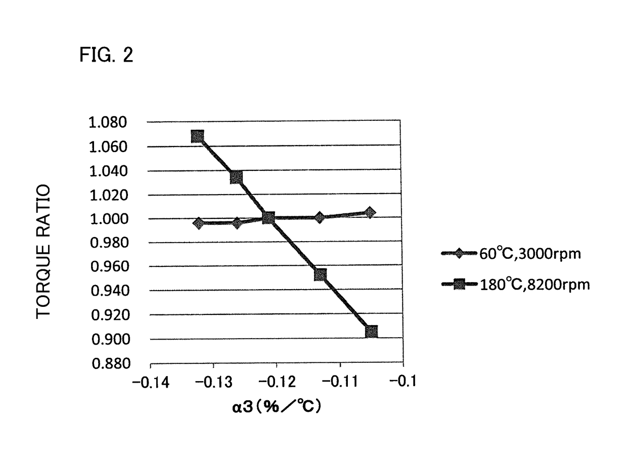
PUM
Abstract
A motor includes a magnet and a coil. α2=[{(Br2−Br1)/Br1}/(T2−T1)]×100≧−0.10 and α3=[{(Br3−Br1)/Br1}/(T3−T1)]×100≦−0.12 are satisfied. In the magnet, Br1 (mT) is a residual magnetic flux density at T1 (° C.), Br2 (mT) is a residual magnetic flux density at T2 (° C.), and Br3 (mT) is a residual magnetic flux density at T3 (° C.), and α2 (%/° C.) is a temperature coefficient at a target temperature of T2 (° C.) with respect to a reference temperature of T1 (° C.), and α3 (%/° C.) is a temperature coefficient at a target temperature of T3 (° C.) with respect to a reference temperature of T1 (° C.) in conditions of T1=23, T2=60, and T3=180.
Description
BACKGROUND OF THE INVENTION1. Field of the Invention[0001]The present invention relates to a motor.2. Description of the Related Art[0002]Patent Document 1 discloses a variable magnetic flux drive system that changes a magnetic force of a magnet in a motor. This system improves its entire efficiency and can correspond to a wide speed range.[0003]However, the system disclosed in Patent Document 1 is complicated in control. Furthermore, the system needs a certain level or more magnetic field to change the magnetic force of the magnet and flows an electric current corresponding to the magnetic field through a coil. To do this, the motor needs to be temporarily stopped for determination of a position of the magnet to the coil. A large magnetic field is necessary for change in magnetization of the magnet, and a coil and a power source for the large magnetic field are a large scale.[0004]Patent Document 1: JP 2008-029148ASUMMARY OF THE INVENTION[0005]The present invention has been achieve...
Claims
Application Information
Patent Timeline
Application Date:The date an application was filed.
Publication Date:The date a patent or application was officially published.
First Publication Date:The earliest publication date of a patent with the same application number.
Issue Date:Publication date of the patent grant document.
PCT Entry Date:The Entry date of PCT National Phase.
Estimated Expiry Date:The statutory expiry date of a patent right according to the Patent Law, and it is the longest term of protection that the patent right can achieve without the termination of the patent right due to other reasons(Term extension factor has been taken into account ).
Invalid Date:Actual expiry date is based on effective date or publication date of legal transaction data of invalid patent.