Bridgeless buck-boost power factor correction converter and control system

A power factor correction, buck-boost technology, used in control/regulation systems, DC power input to DC power output, output power conversion devices, etc., can solve problems such as low device utilization, and achieve zero-current shutdown Simple implementation, increased control complexity, and simple system control implementation

Active Publication Date: 2022-01-18
SOUTHWEST JIAOTONG UNIV
View PDF13 Cites 0 Cited by
  • Summary
  • Abstract
  • Description
  • Claims
  • Application Information

AI Technical Summary

Problems solved by technology

Therefore, only one group of devices is used in half the power frequency cycle, and the device utilization rate is low

Method used


Image

  • Bridgeless buck-boost power factor correction converter and control system
  • Bridgeless buck-boost power factor correction converter and control system
  • Bridgeless buck-boost power factor correction converter and control system

Examples


Embodiment 1

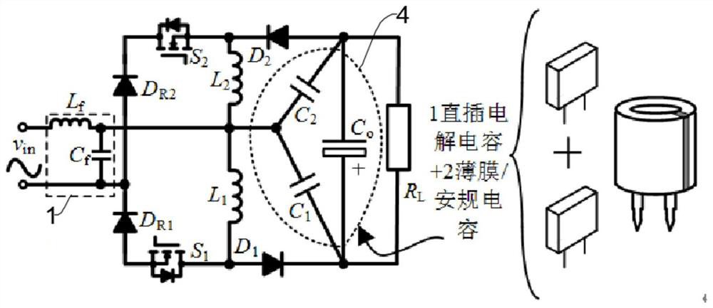
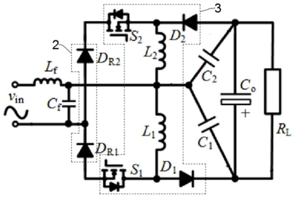
[0041] This embodiment provides a bridgeless buck-boost power factor correction converter, including a conversion circuit, the conversion circuit includes an input filter unit 1, a rectifier unit 2, a buck-boost unit 3 and an output capacitor unit 4 connected in sequence; the above The output capacitor unit 4 includes the output capacitor C 1 , the output capacitance C 2 and main output capacitor C 0 , above the output capacitor C 1 One end of the output capacitor with the above C 2 connected at one end, above the output capacitor C 1 The other end of the above-mentioned buck-boost unit 3 and the main output capacitor C 0 The positive terminal is connected above the output capacitor C 2 The other end of the above-mentioned buck-boost unit 3 and the main output capacitor C 0 The negative terminal connection; the above output capacitor C 1 with the above output capacitor C 2 The interconnection terminals of the above-mentioned buck-boost unit and the 3-input filter unit ...

Embodiment 2

[0047] In this embodiment, the above-mentioned converter includes two working modes, when the AC input v in During zero-cross commutation, the converter works in mode A, when the AC input v in During non-zero-crossing commutation, the converter works in mode B.

[0048] Since the operation of the bridgeless buck-boost PFC converter of the present invention is similar in the positive half cycle and the negative half cycle of the AC input, this embodiment only uses the operation of the positive half cycle as an example to illustrate the working principle of the converter.

[0049] The converter of the present invention application has A, B two kinds of working modes: (1) when the AC input v in At zero-crossing commutation, the converter works in mode A, and working mode A is as follows Figure 3(a) ~ 3(c) Shown; (2) When the AC input v in At the non-zero-crossing commutation place, the converter works in mode B, and the working mode B is as follows Figure 4(a) ~ 4(d) shown....

Embodiment 3

[0065] like Figure 7 As shown, this embodiment provides a control system, including the above-mentioned converter and a control circuit for controlling the converter to realize constant current output, and the control circuit is connected to the output end of the conversion circuit.

[0066] Since the buck-boost PFC converter is commonly used in LED driving devices, the present invention applies a constant current output control method. Wherein the control circuit includes a sampling proportional amplification circuit K i , adder and subtractor, PI parameter operator, comparator and drive circuit; the output terminal of the conversion circuit is in the main output capacitor C 0 with load R L connected between the output current sense resistor R i ;

[0067] The output current sense resistor R i The voltage on the sample is sampled and passed through the proportional amplification circuit K i After adding and subtracting with the reference current I refTo compare, the g...


PUM


Abstract

The invention discloses a bridgeless buck-boost power factor correction converter and a control system, and relates to the field of electric energy conversion. The bridgeless buck-boost power factor correction converter comprises a conversion circuit, and the conversion circuit comprises an input filtering unit, a rectification unit, a buck-boost unit and an output capacitor unit which are connected in sequence. The buck-boost unit comprises a switching tube S1, an inductor L1, a diode D1, a switching tube S2, an inductor L2 and a diode D2, the output capacitor unit comprises an output capacitor C1, an output capacitor C2 and a main output capacitor C0, one end of the output capacitor C1 is connected with one end of the output capacitor C2, the other end of the output capacitor C1 is connected with the positive end of the main output capacitor C0, and the other end of the output capacitor C2 is connected with the negative end of the main output capacitor C0. According to the converter provided by the invention, the topological structure of the output capacitor in the conversion circuit is improved to realize time division multiplexing of the inductor, and the utilization rate of the device is improved.

Description

technical field [0001] The invention relates to the technical field of electric energy conversion, in particular to a bridgeless buck-boost power factor correction converter and a control system. Background technique [0002] AC-DC power factor correction (Power factor correction, PFC) converter has been widely researched and applied because it can meet the grid harmonic requirements and power factor (Power factor, PF) requirements. Buck-boost PFC converter is widely used in LED lighting and brushless DC motors due to its advantages of high PF value and variable output voltage. [0003] In recent years, as the country vigorously calls for low-carbon life and energy conservation policies, bridgeless buck-boost PFC converters without rectifier bridges have received extensive attention and research. Its essence is to no longer use a rectifier bridge composed of four rectifier diodes, thereby reducing the number of current path diodes and obtaining higher system efficiency. ...

Claims


Application Information

Patent Timeline
Patent Type & Authority Applications(China)
IPC IPC(8): H02M3/158H02M1/12H02M1/32H02M1/42
CPCH02M3/1582H02M1/126H02M1/32H02M1/4225Y02B70/10
Inventor 陈正格
Owner SOUTHWEST JIAOTONG UNIV
Why Eureka
Try Eureka