Bus system design method, bus system, and device unit

Inactive Publication Date: 2005-02-24
FUJITSU LTD
View PDF2 Cites 0 Cited by
  • Summary
  • Abstract
  • Description
  • Claims
  • Application Information

AI Technical Summary

Benefits of technology

(1) Even when data communications is being performed through a data bus, device units can be connected or disconnected. Thus, the bus system, in addition to being able to enhance system reliability, is very convenient for use.
(2) Since there is no possibility that noise, caused by connecting a device unit on a data bus being active, will have an adverse influence on other device units connected on this data bus or devices connected on the data bus, device units can be connected on the data bus being active, without stopping the transmission of data through the data bus. Thus, in addition to being able to enhance data transmission efficiency, there is no need to monitor whether or not a device unit is inserted in the data bus, and there is no need to perform a variety of controls for stopping the PCI bus. Therefore, system controls can be simplified and development and operating costs can be reduced.
(3) If the connection timing between the device unit and the data bus is computed by computing a delay time “b” needed for the bus switch to connect the device unit on the data bus after the connecti

Problems solved by technology

If the host interface module is connected on the PCI bus of the mother board being active (active insertion), noise occurs on the PCI bus because of that active connection and has an adverse influence on the operation of other host interface modules connected on the PCI bus and operation of various devices constituting the mother board.
However, if the bus operation of the PCI bus is stopped in order to insert host interface modules, data transmission through the PCI bus can

Method used


Image

  • Bus system design method, bus system, and device unit
  • Bus system design method, bus system, and device unit
  • Bus system design method, bus system, and device unit

Examples


Embodiment Construction

A preferred embodiment of the present invention will hereinafter be described in detail with reference to the drawings.

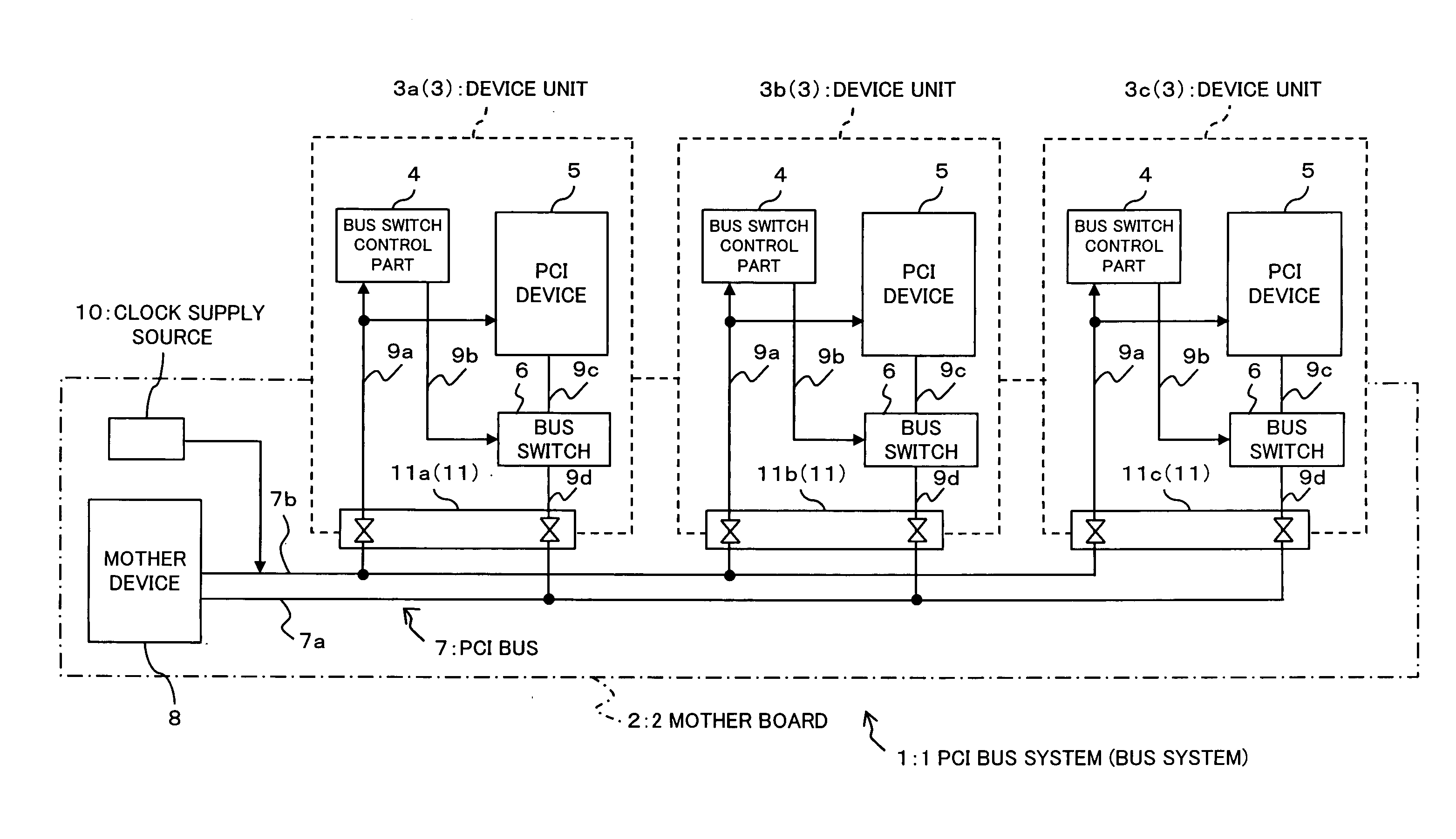
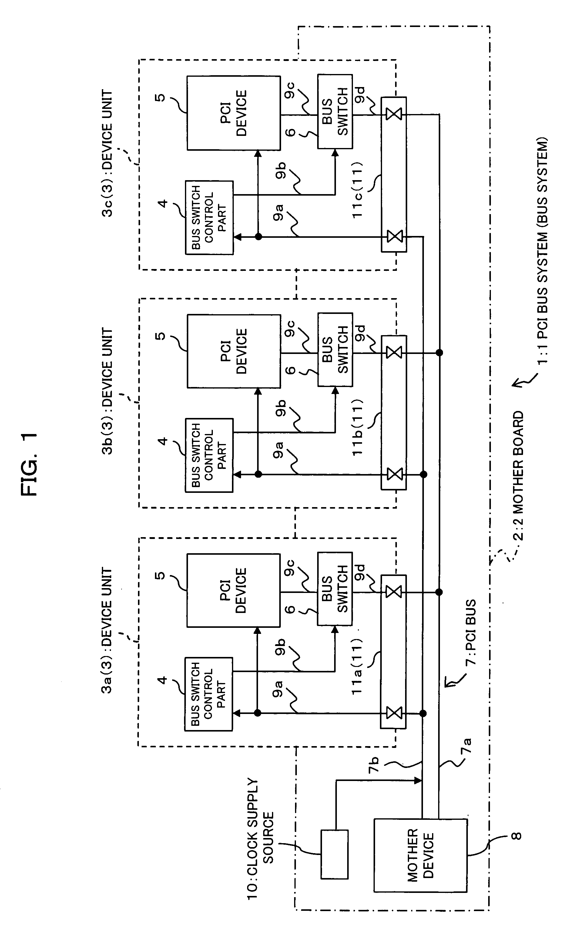
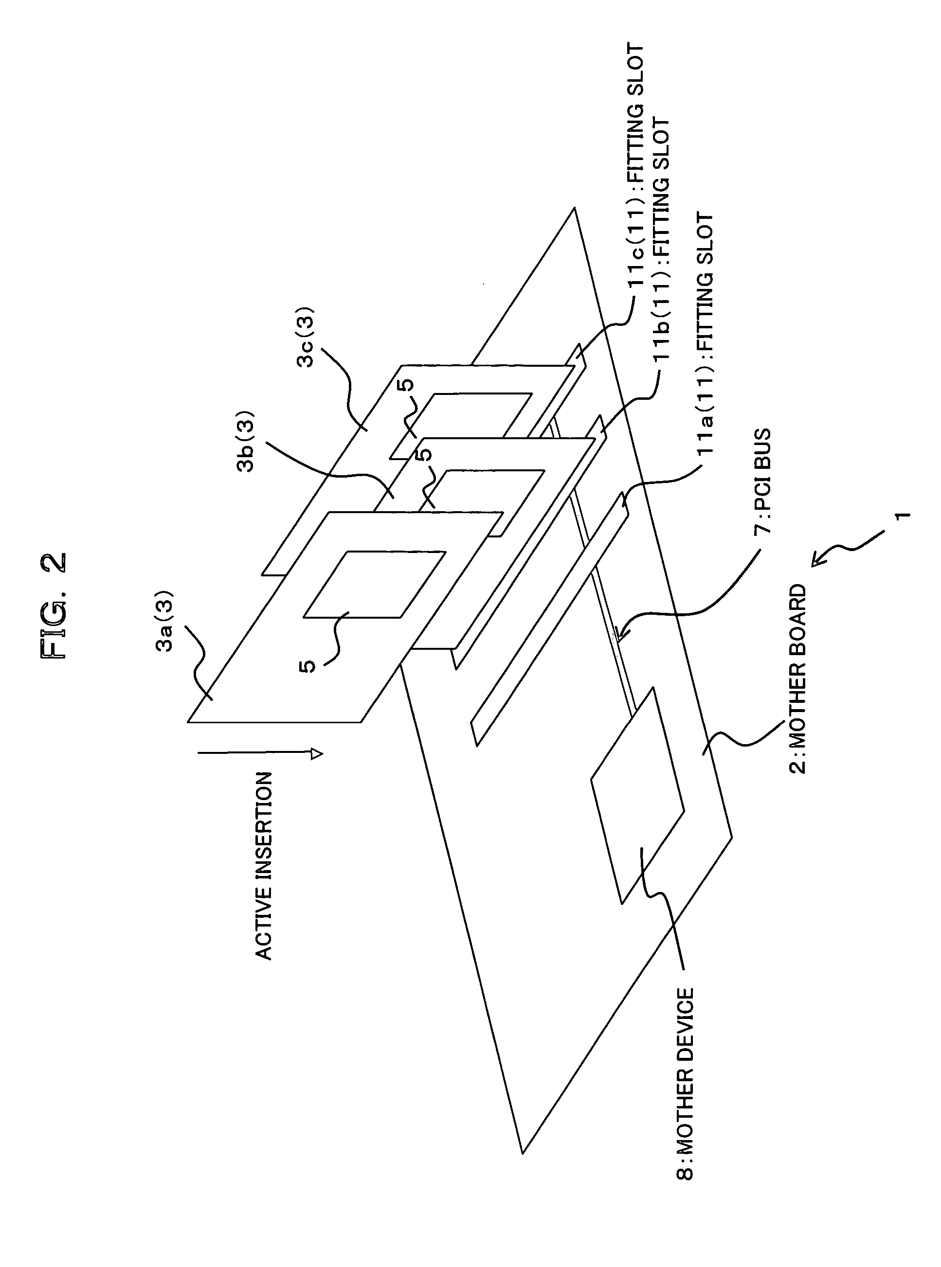
A bus system as a preferred embodiment of the present invention is, for example, a PCI bus system with a PCI bus employed in a storage system, etc. The storage system is equipped with a plurality of disk units (magnetic disk units, physical device units) and writes the data from a server (host) to these disk units in response to access from the server and reads out the data requested by the server from the disk units and transmit that data. The PCI bus system is used for transmitting and receiving data signals.

The above-described storage system is equipped with a host interface module, which transmits data to a server through a fiber channel interface bus. This host interface module is connected to a PCI bridge module through an interface bus such as a PCI bus and is used to transmit data to a disk interface module, management module, etc., connected to the PCI m...


PUM


Abstract

A design method for a bus system comprising a noise propagation computation step and a connection timing computation step. Based on the cycle of a timing signal, a signal propagation delay in a device unit, signal propagation delays in a timing-signal bus and a data bus, and a setup time in the device unit or device connected on the data bus, the noise propagation computation step computes timing at which, when the device unit is connected on the data bus being active, noise propagates to other device units other than the connected device unit or to the device connected on the data bus. Based on the timing computed in the noise propagation computation step, the connection timing computation step computes connection timing at which the device unit is connected on the data bus.

Description

BACKGROUND OF THE INVENTION (1) Field of the Invention The present invention relates to a bus system in which a plurality of device units are connectible on the same bus, like a peripheral component interconnect (PCI) bus system employed in a storage system. The invention also relates to a bus system design method suitable for designing that bus system, and a device unit connectible to that bus system being in an active state. (2) Description of Related Art For example, a storage system is equipped with a plurality of disk units (magnetic disk units, physical device units), and is used for writing the data from a server (host) to these disk units in response to access from the server, or reading out the data requested by the server from the disk units and transmitting that data. Such a storage system includes a host interface module, which transmits data to the server through a fiber channel interface bus. The host interface module is connected to a PCI bridge module through an...

Claims


Application Information

Patent Timeline
IPC IPC(8): G06F3/00G06F13/40G06F13/42H04L7/00H05K9/00
CPCG06F13/4081H05K9/0069H04L7/0008G06F2213/0024
Inventor NISHIMIYA, RYOHEI
Owner FUJITSU LTD
Why Eureka
Try Eureka