Ceiling light with an oblong light housing

Inactive Publication Date: 2006-01-26
A RAYMOND & CO
View PDF5 Cites 6 Cited by
  • Summary
  • Abstract
  • Description
  • Claims
  • Application Information

AI Technical Summary

Benefits of technology

[0008] This configuration allows not only significantly reduced production costs, but also simplified handling during assembly of the light housing and above all during the opening and closing of the bottom part when the fluorescent tubes are changed. Through the one-piec

Problems solved by technology

The closing element is very complicated and labor-intensive for the assembly of the ceiling light.
Also, too much is asked of the assembler for the changing of defective fluorescent tubes, which can rarely be complet

Method used


Image

  • Ceiling light with an oblong light housing
  • Ceiling light with an oblong light housing

Examples


Example

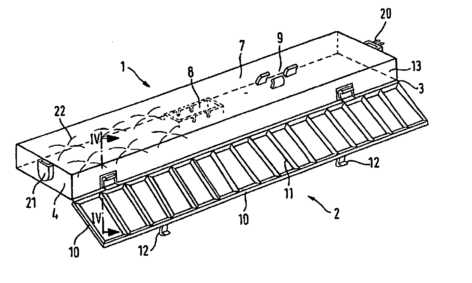
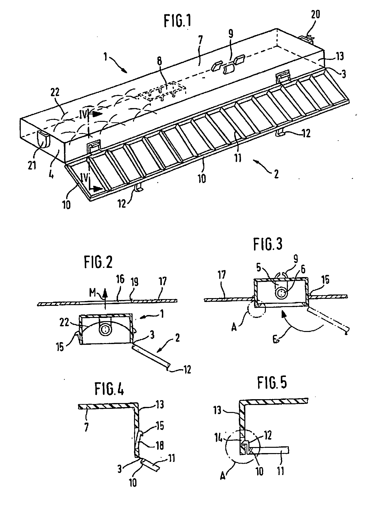
[0016] The ceiling light shown in the figures essentially comprises an elongated, trough-shaped top part 1 and a transparent bottom part 2. Both parts are injection molded in one piece from plastic and connected to each other so that they can pivot about a longitudinal edge by means of a so-called film hinge 3.

[0017] The top part 1 is provided on the insides of both end walls 4 with brackets 5 for holding at least one fluorescent tube 6. In the ceiling 7 of the top part 1, holders 8 and clamps 9 for the associated ballasts and cable lines are also integrated, which are typically needed for operating fluorescent tubes 6.

[0018] The bottom part 2 comprises a frame 10 with connecting ribs 11 extending transversely over the entire length and with a V-shaped cross-sectional profile. For detachable fastening of the bottom part 2 on the top part 1, locking elements 12 are formed on the frame 10 on the side opposite the film hinge 3 (FIGS. 3 and 5). These locking elements 12 engage in corr...


PUM


Abstract

The invention relates to a ceiling light with an oblong light housing. The above comprises a dished upper piece (1), provided with brackets (5), for mounting at least one fluorescent tube (6), fixings (8) and clamps (9), for the corresponding electrical ballast devices and cables and fixing elements for securing the upper piece (1) to a ceiling board (17) and a transparent lower piece (2), provided with detachable clip elements (12), for connection to the upper piece (1). The upper piece (1) and the lower piece (2) are moulded from hard elastic plastic and pivotably connected to each other along a longitudinal edge by means of a so-called integral hinge (3).

Description

CROSS-REFERENCE TO RELATED APPLICATIONS [0001] This application is a National Stage of International Application No. PCT / EP03 / 08282, filed on Jul. 26, 2003, which claims priority to German Patent Application No. 102 36 500.8, filed on Aug. 9, 2002. The disclosures of the above applications are incorporated herein by reference.BACKGROUND OF THE INVENTION [0002] The invention pertains to a ceiling light with an elongated light housing, comprising a trough-shaped top part, which is provided with brackets for holding at least one fluorescent tube, with holders for the associated electrical ballasts and cables, and also with fastening elements for anchoring the top part in the ceiling, and a transparent bottom part supported so that it can pivot about a longitudinal edge of the top part with detachable locking elements for connecting to the top part. [0003] Ceiling lights of this type are generally known and are used especially for illuminating office spaces, factory spaces, warehouses, ...

Claims


Application Information

Patent Timeline
IPC IPC(8): F21S8/00F21S4/00F21S8/02F21V17/00F21S8/04F21V15/01F21V17/10F21V21/04F21V23/06F21Y103/00
CPCF21S8/02F21V15/01F21Y2103/00F21V21/04F21V23/06F21V17/107
Inventor LEGAT, JEAN-JACQUESGIRARD, DIDIER
Owner A RAYMOND & CO
Why Eureka
Try Eureka