
Method of compensating for an effect of temperature on a control system

a control system and temperature technology, applied in the field of photography, can solve the problems of camera shake becoming a limiting factor in the ability of photographers to take unblurred photographs, the inability to readily find or use a tripod in a particular photographic situation, and the blur caused by camera shak

Inactive Publication Date: 2006-01-26
HEWLETT PACKARD DEV CO LP
View PDF56 Cites 29 Cited by
  • Summary
  • Abstract
  • Description
  • Claims
  • Application Information

AI Technical Summary

Benefits of technology

[0014] A method of compensating for an effect of temperature comprises characterizing the performance of a control system that performs image stabilization by moving an electronic array light sensor in relation to a lens, and adjusting a control system parameter when the performance departs significantly from a nominal performance due to an effect of temperature.

Problems solved by technology

Image blur caused by camera shake is a common problem in photography.
The problem is especially acute when a lens of relatively long focal length is used, because the effects of camera motion are magnified in proportion to the lens focal length.
Especially at the longer focal length settings, camera shake may become a limiting factor in a photographer's ability to take an unblurred photograph, unless corrective measures are taken.
However, a tripod may not be readily available or convenient in a particular photographic situation.
Using a faster shutter speed is not always feasible, especially in situations with dim lighting.
Shutter speed may be increased if a larger lens aperture is used, but larger-aperture lenses are bulky and expensive and not always available.

Method used


Image

  • Method of compensating for an effect of temperature on a control system
  • Method of compensating for an effect of temperature on a control system
  • Method of compensating for an effect of temperature on a control system

Examples


Embodiment Construction

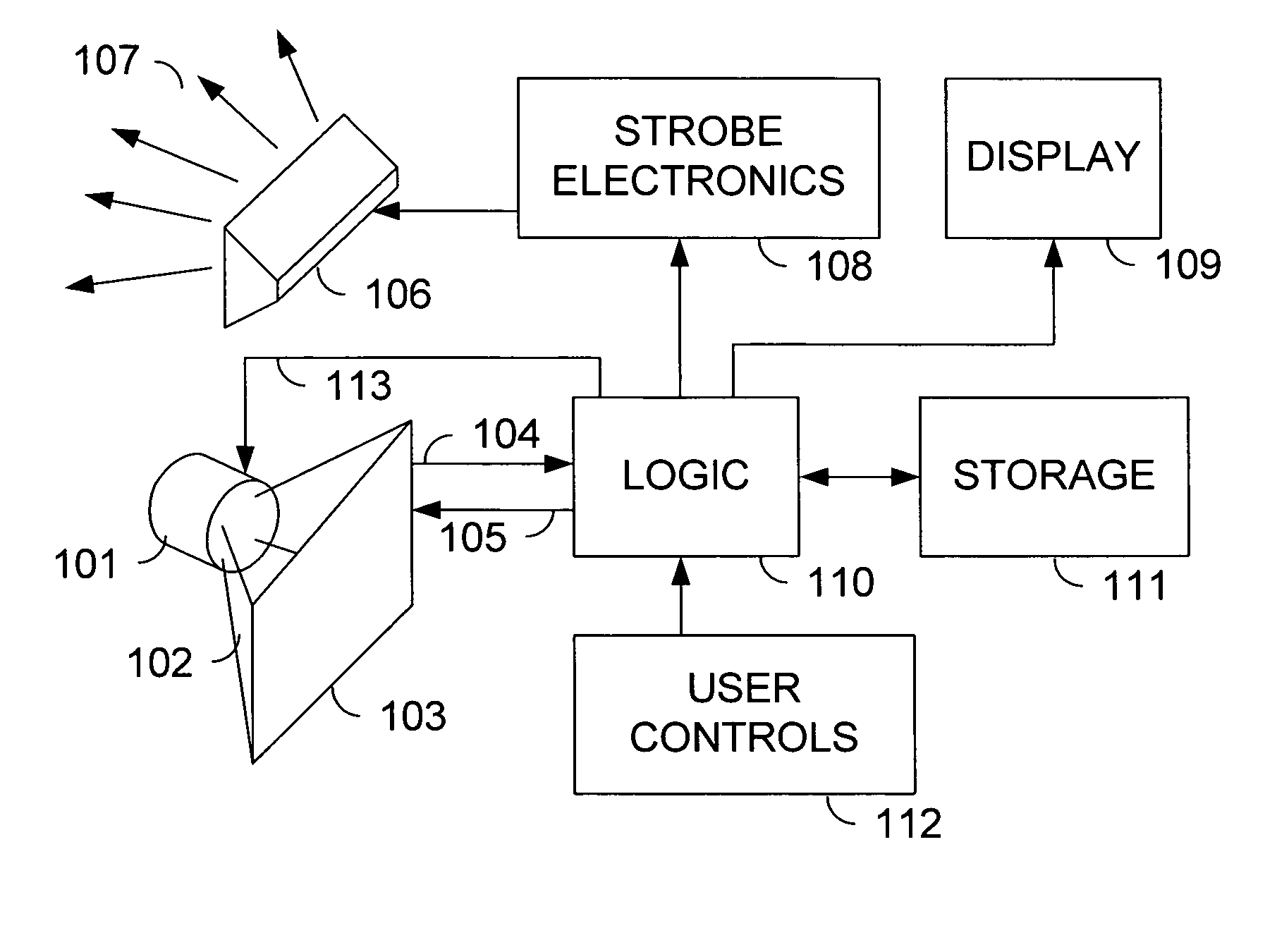
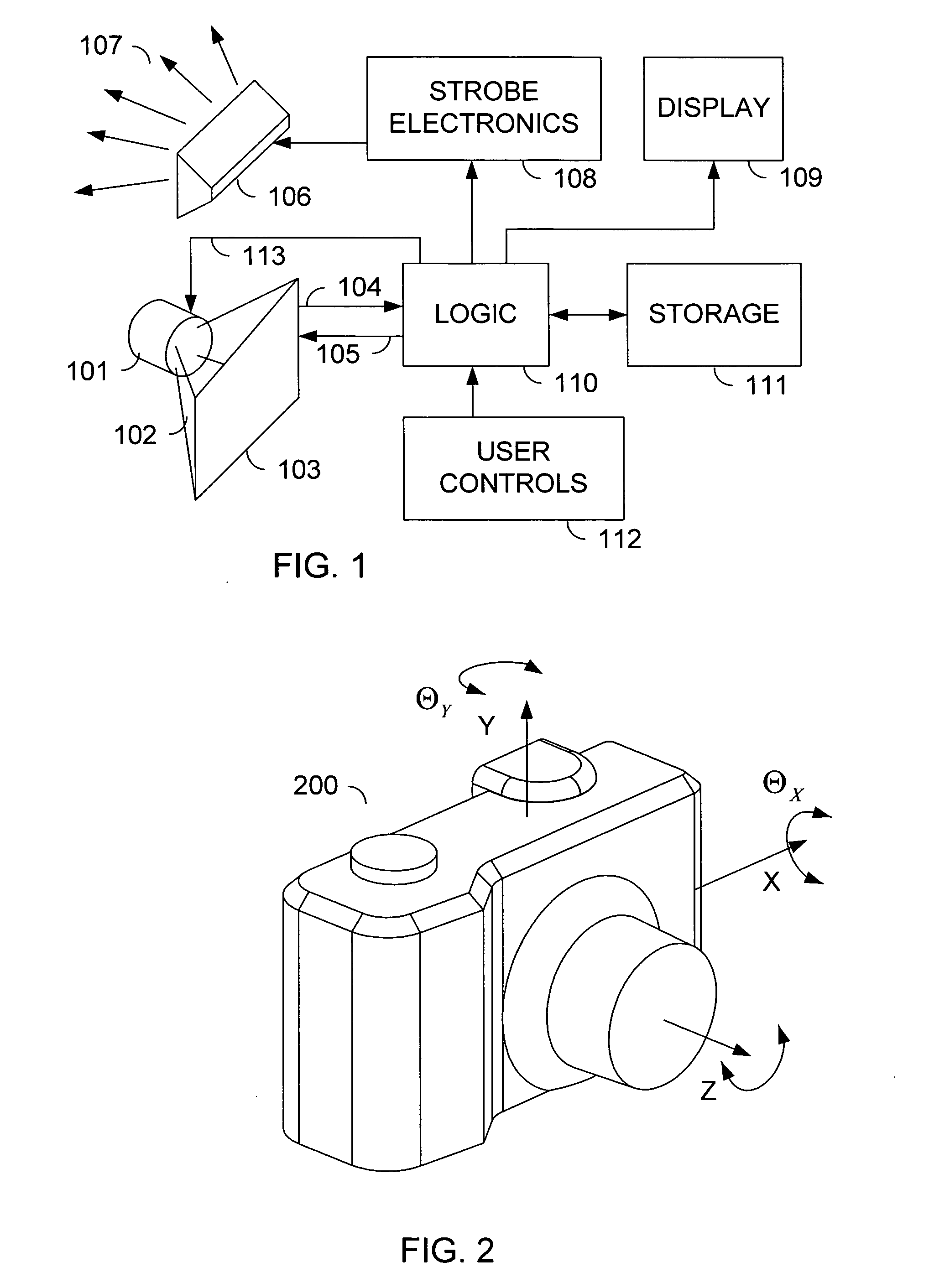
[0035]FIG. 1 shows a simplified block diagram of a digital camera. A lens 101 gathers light emanating from a scene, and redirects the light 102 such that an image of the scene is projected onto an electronic array light sensor 103. Electronic array light sensor 103 may be an array of charge coupled devices, commonly called a “CCD array”, a “CCD sensor”, or simply a “CCD”. Alternatively, electronic array light sensor 103 may be an array of active pixels constructed using complementary metal oxide semiconductor technology. Such a sensor may be called an “active pixel array sensor”, a “CMOS sensor”, or another similar name. Other sensor technologies are possible. The light-sensitive elements on electronic array light sensor 103 are generally arranged in an ordered rectangular array, so that each element, or “pixel”, corresponds to a scene location.

[0036] Image data signals 104 are passed to logic 110. Logic 110 interprets the image data signals 104, converting them to a numerical repr...


PUM


Abstract

A sensor mounting system for enabling image stabilization in a digital camera is described. An electronic array light sensor is moved in relation to other parts of the camera in response to camera motion. In one embodiment, the sensor is moved by at least one linear motor having a ferrofluid in a gap of the linear motor. Other aspects of the system are described, including methods of heat sinking the sensor, a suspension system, methods of compensating for an effect of temperature on the ferrofluid, and a compact magnet configuration for forming the linear motor and providing feedback as to the position of the sensor.

Description

CROSS REFERENCE TO RELATED APPLICATIONS [0001] This application is related to the following applications, all of which are filed on the same date as this application, and all of which are assigned to the assignee of this application: [0002] Ferrofluid suspension for image stabilization (U.S. application Ser. No. ______ not yet assigned); [0003] Apparatus and method for heat sinking a sensor (U.S. application Ser. No. ______ not yet assigned); [0004] Flexible suspension for image stabilization (U.S. application Ser. No. ______ not yet assigned); and [0005] Magnet configuration for image stabilization (U.S. application Ser. No. ______ not yet assigned).FIELD OF THE INVENTION [0006] The present invention relates generally to photography, and more specifically to image stabilization. BACKGROUND OF THE INVENTION [0007] Image blur caused by camera shake is a common problem in photography. The problem is especially acute when a lens of relatively long focal length is used, because the effe...

Claims


Application Information

Patent Timeline
Patent Type & Authority Applications(United States)
IPC IPC(8): G03B17/00H04N5/232H04N5/349H04N5/369
CPCG03B17/02H04N5/23287H04N5/23248H04N5/2253H04N23/54H04N23/68H04N23/687
Inventor STAVELY, DONALD J.
Owner HEWLETT PACKARD DEV CO LP
Learn More