
Intracranial pressure monitoring system

a monitoring system and intracranial pressure technology, applied in the field of medical devices, can solve the problems of intermittent nature of measurement obtained by conventional implanted telemetric icp monitors, inconvenient and discomfort associated with external, catheter-based icp monitors, and difficult for a care-giver to obtain continuous icp measurements over an extended period, so as to improve patient care

Inactive Publication Date: 2006-01-26
MEDTRONIC INC
View PDF33 Cites 49 Cited by
  • Summary
  • Abstract
  • Description
  • Claims
  • Application Information

AI Technical Summary

Benefits of technology

The invention is a system and method for monitoring intracranial pressure (ICP) in a patient using an inductive power element that extends over the patient's head. This allows for continuous or periodic measurement of ICP over an extended period of time, without the need for a persistent, catheter-based monitor. The system includes an inductive power transmitting element and an external monitor to receive the transmitted ICP signals. The invention provides a valuable body of information that allows caregivers to detect potentially dangerous ICP levels and improve patient care. The system is comfortable and convenient for patients.

Problems solved by technology

These problems include the inconvenience and discomfort associated with external, catheter-based ICP monitors, and the intermittent nature of measurements obtained by conventional implanted telemetric ICP monitors.
Consequently, it is difficult for a care-giver to obtain continuous ICP measurements over an extended period of time using an implanted, telemetric ICP monitor.
As a further problem, a care-giver is unable to detect significantly elevated ICP levels that may occur between intermittent measurements.
The inability to detect elevated ICP levels between measurements can expose the patient to health risks.

Method used


Image

  • Intracranial pressure monitoring system
  • Intracranial pressure monitoring system
  • Intracranial pressure monitoring system

Examples


Embodiment Construction

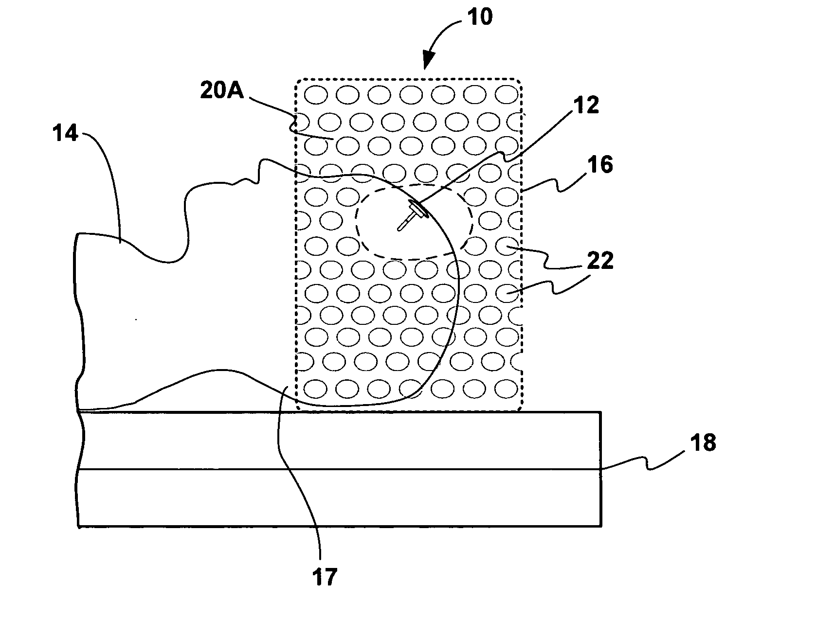
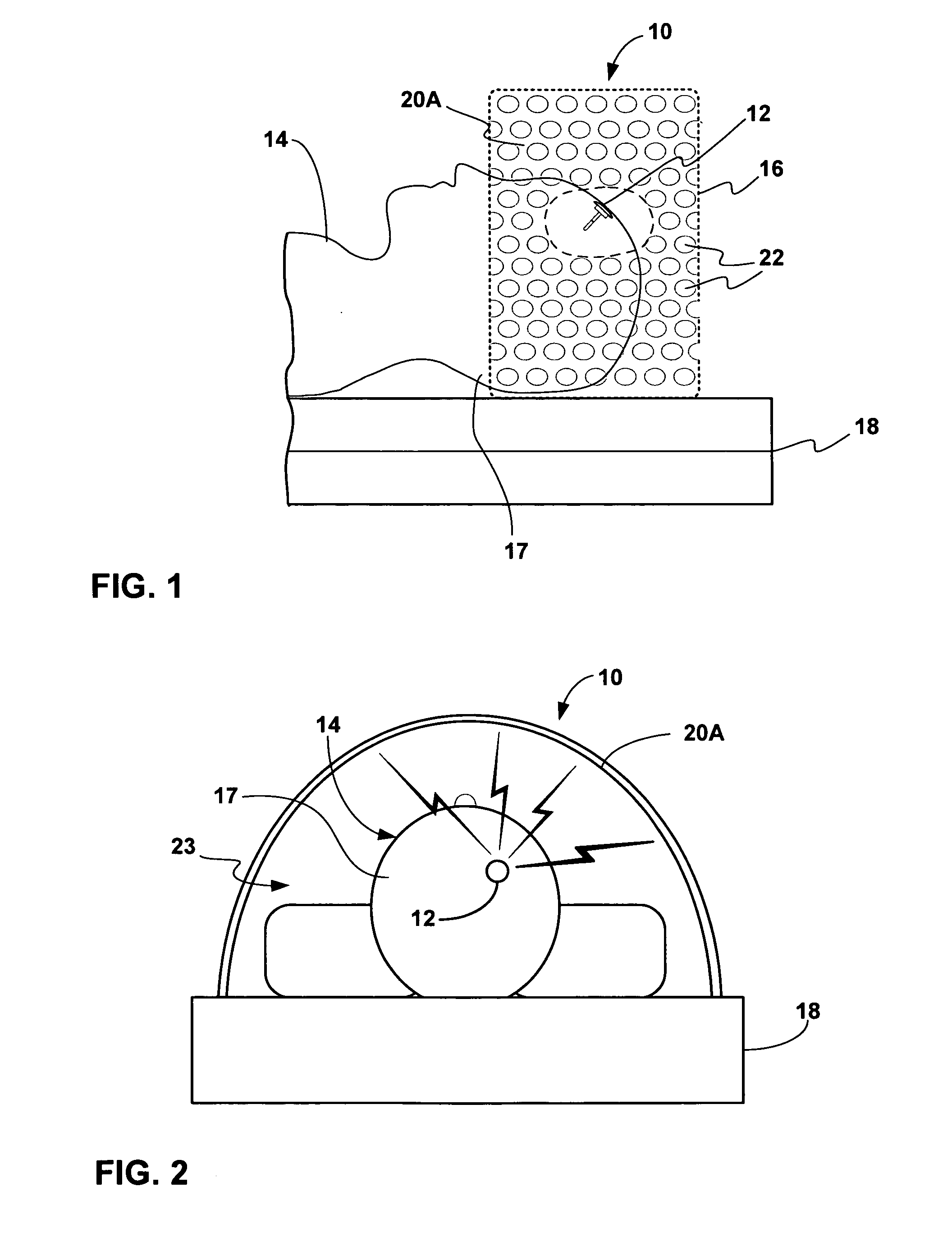
[0028]FIG. 1 is a side view illustrating an ICP monitoring system 10 in conjunction with a patient 14, in accordance with an embodiment of the invention. As shown in FIG. 1, system 10 includes an implantable ICP monitor 12, which has been implanted in the cranium of patient 14 to obtain ICP measurements. In addition, system 10 includes a shroud-like element 16 that extends over a substantial portion of the patient's head, including the portion in which ICP monitor 12 is implanted. As will be described, shroud-like element 16 may serve as both an inductive power transmitting element and a telemetry receiver antenna.

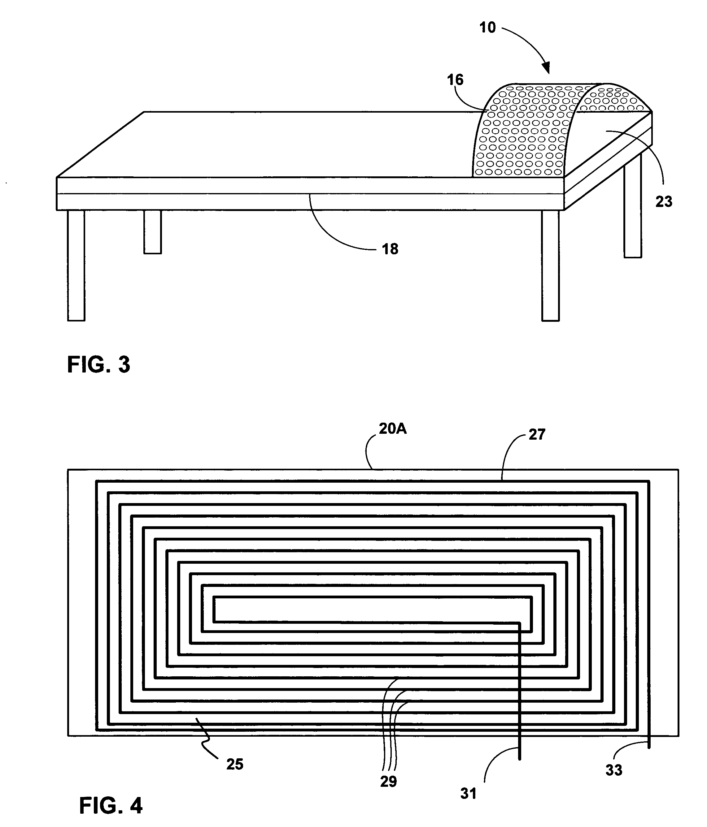
[0029] In some embodiments, shroud-like element 16 defines a tube- or arc-like opening to receive the patient's head 17. Shroud-like element 16 may be mounted to a bed 18, and is constructed, at least partially, from an electrically conductive frame 20A. In other embodiments, shroud-like element 16 may be mounted to a table, chair or other support platform for patient 14....


PUM


Abstract

The disclosure is directed to a system and method for monitoring ICP within a patient on a continuous or periodic basis over an extended period of time. In some situations, a care-giver may want to record ICP measurements over a longer period of time to obtain trend data. A system for monitoring ICP includes a shroud-like, inductive power transmitted element designed to surround at least a substantial portion of a patient's head and power an implanted ICP monitor. The shroud-like element may be a table-mounted device that arcs over the width of the table or bed, providing room for the patient's head.

Description

[0001] This application claims the benefit of U.S. provisional application No. 60 / 589,347, filed Jul. 20, 2004, the entire content of which is incorporated herein by reference.FIELD OF THE INVENTION [0002] The invention relates to medical devices and, more particularly, devices for draining cerebral spinal fluid. BACKGROUND [0003] Hydrocephalus is an excess accumulation of cerebrospinal fluid (CSF) in the ventricles of the brain. This fluid, which protects, nourishes and cleanses the brain and spinal cord, is manufactured daily in the ventricles. Buildup of CSF occurs when the fluid cannot flow freely throughout the ventricles and the central nervous system due to various forms of blockage. Except in very rare cases, hydrocephalus is a life-long condition that can only be controlled, not cured, through medical intervention. There are a number of accepted treatments available for hydrocephalus, most of which involve the surgical implantation of a shunt. The shunt diverts CSF from the...

Claims


Application Information

Patent Timeline
Patent Type & Authority Applications(United States)
IPC IPC(8): A61B5/00
CPCA61B2560/0219A61B5/031
Inventor GEIGER, MARK A.
Owner MEDTRONIC INC
Learn More