Image recording apparatus

a recording apparatus and image technology, applied in the direction of printing, other printing apparatus, etc., can solve the problems of large amount of paper dust, dust or air that cannot be properly discharged to the outside of the apparatus, but remains in the apparatus, etc., and achieve the effect of high reliability

Active Publication Date: 2006-02-02
RISO KAGAKU CORP
View PDF2 Cites 23 Cited by
  • Summary
  • Abstract
  • Description
  • Claims
  • Application Information

AI Technical Summary

Benefits of technology

[0012] There is provided an image recording apparatus which prevents an ink jet head from not ejecting ink drops and ejecting ink drops curvedly because of paper dust and dust in the air, and prevents dust from intruding into the apparatus from outside, thereby recording a high-quality image with high reliability.

Problems solved by technology

This contact generates a large amount of paper dust from the recording medium in the apparatus.
Since the Publication does not take into consideration the flow path of the conveyance mechanism housing 101 or the flow path between the wind-direction guide 104 and a recording medium, there is fear that dust or air will not properly be discharged to the outside of the apparatus but remain in the apparatus.
If the dust 113 is attached to the nozzle 140, there is fear that the ink drops will not be ejected or ejected curvedly to cause displacements and blur of an image and thus lower its quality remarkably.
Thus, the ink drops do not land in a proper position to degrade the quality of a recorded image remarkably.
Furthermore, there is fear that dust or air will not properly be discharged to the outside of the apparatus but remain in the apparatus since the wind-direction guide is provided.

Method used


Image

  • Image recording apparatus
  • Image recording apparatus
  • Image recording apparatus

Examples


first embodiment

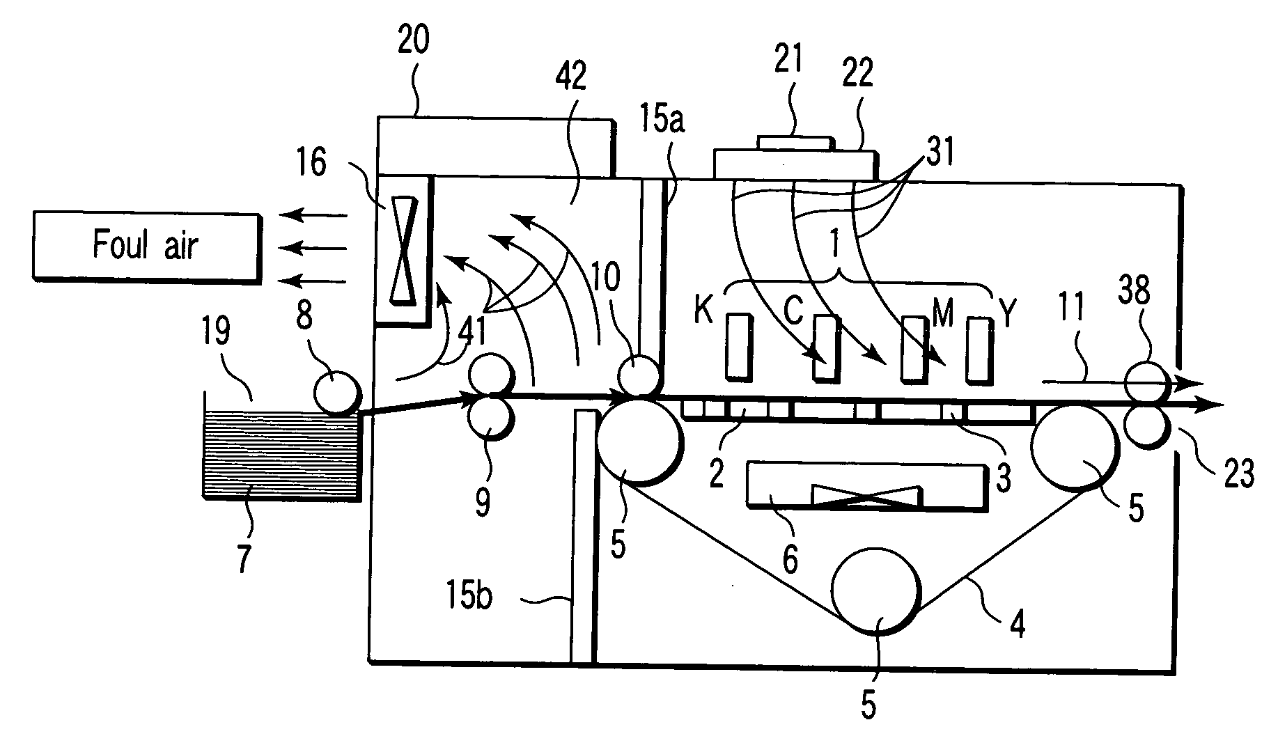
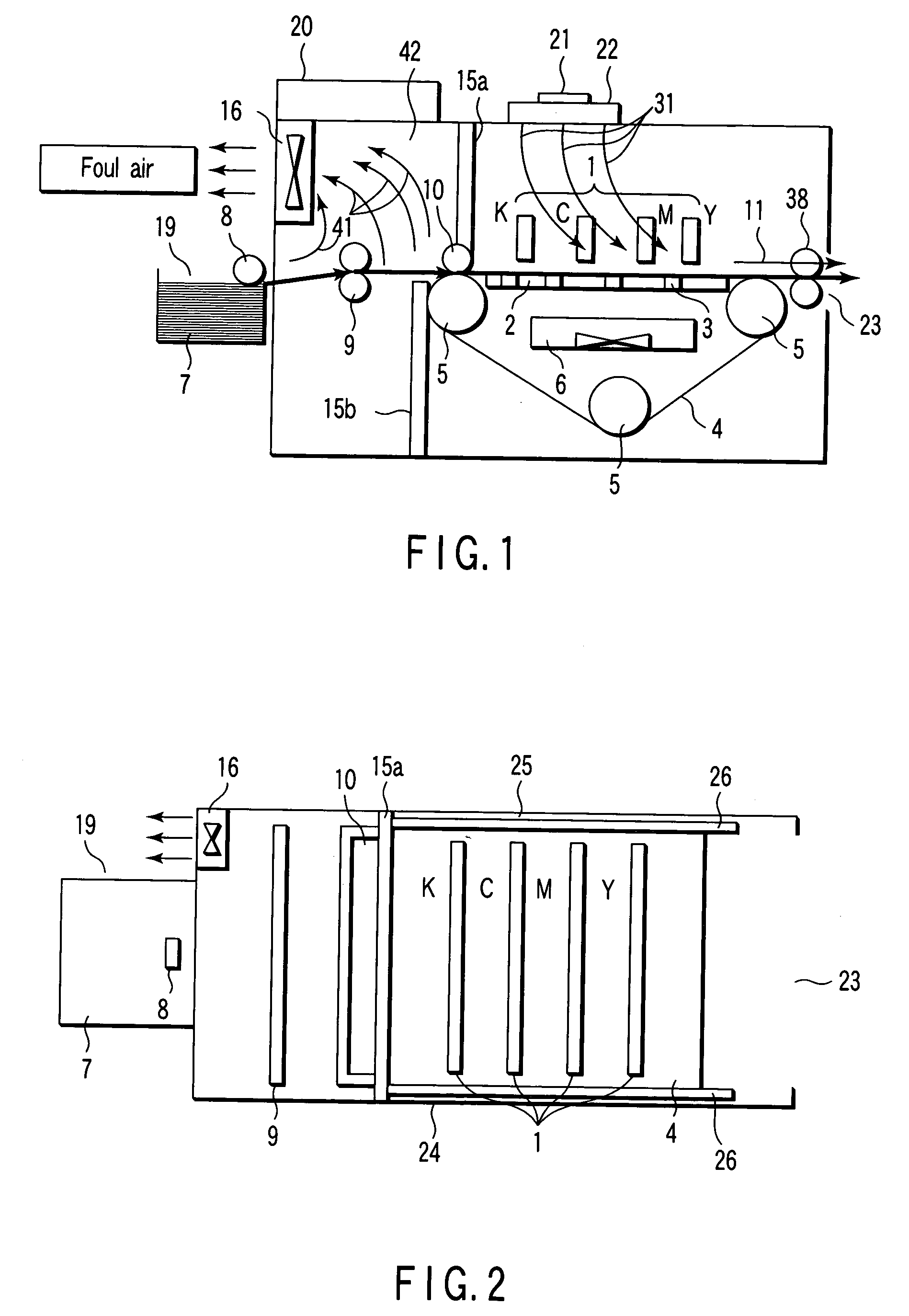
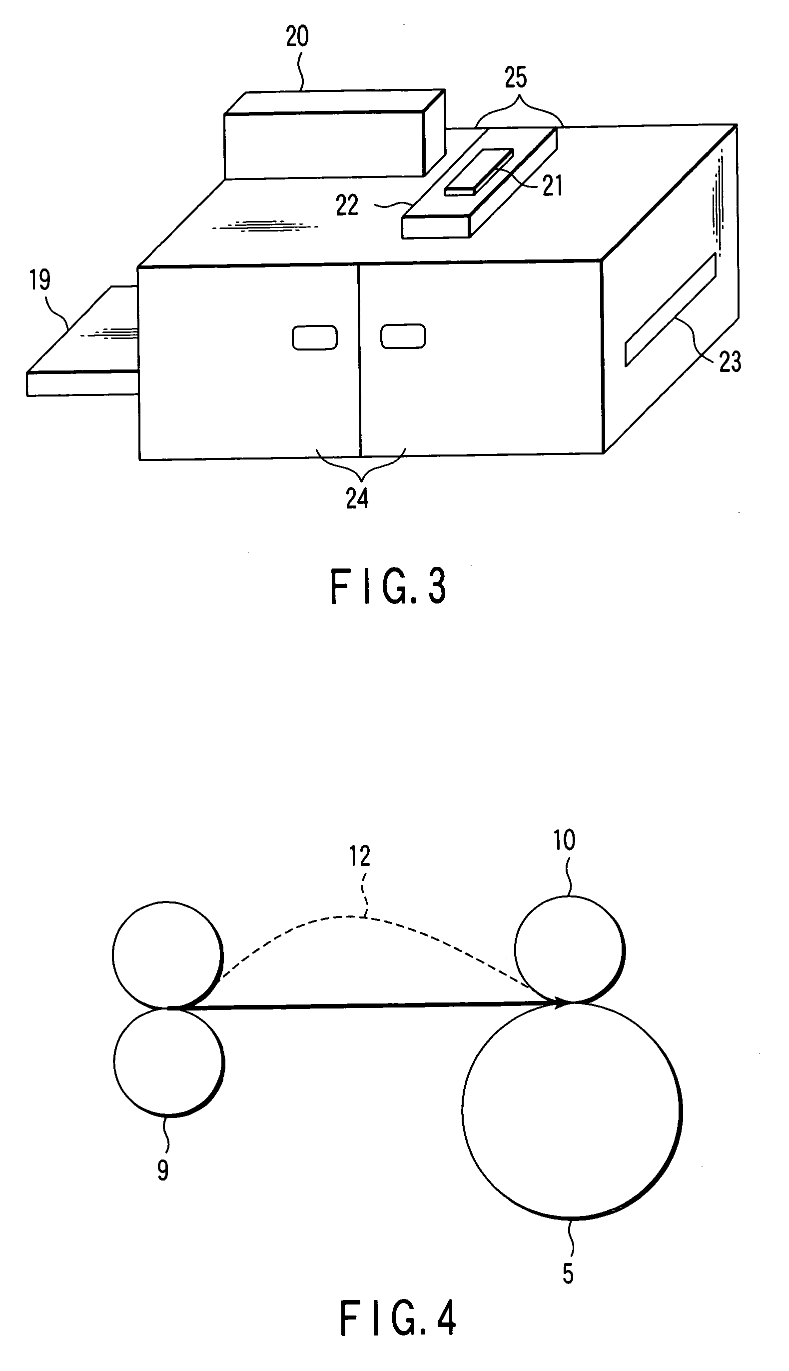
[0032] An image recording apparatus according to the present invention will be described with reference to FIGS. 1, 2, 3 and 6. FIG. 1 is a schematic diagram of the internal structure of the image recording apparatus. FIG. 2 is a cross-sectional view of the image recording apparatus. FIG. 3 is a perspective view of the image recording apparatus. FIG. 6 is a sectional view taken from a discharge outlet 23 of the image recording apparatus.

[0033] The image recording apparatus comprises an ink jet head 1 including a plurality of nozzles capable of ejecting ink of different colors, such as black (K), cyan (C), magenta (M) and yellow (Y) and then recording color images. These nozzles are arranged in the same direction as the conveyance direction and each have an ejecting outlet for ejecting ink in the gravitational direction (vertical direction).

[0034] In the first embodiment, the ink jet head 1 can be formed as a nozzle array having such a length as to cover the recording (maximum width...

second embodiment

[0057] An image recording apparatus according to the present invention will be described with reference to FIG. 9.

[0058] The same constituting elements as those of the first embodiment are indicated by the same reference numerals and their detailed descriptions are omitted. In the second embodiment, an opening 36 is formed in the top of an ink jet head 1 that is interposed between two guide plates 26, as shown in FIG. 9.

[0059] The apparatus of the second embodiment has a function of preventing dust from intruding into the ink jet head 1 by clean air 31 that is blown from a fan unit 21 with a filter through a duct 22. The apparatus also has a function of cooling heat generated from a head driving substrate 37, which is arranged between the opening 36 and the ink jet head 1, by blowing clean air 31 directly into the substrate 37. The clean air 31 that has cooled the head driving substrate 37 flows toward a conveyor belt 4. The substrate 37 can thus be cooled without using any dedicat...

third embodiment

[0061] An image recording apparatus according to the present invention will be described with reference to FIG. 10.

[0062] The same constituting elements as those of the first embodiment are indicated by the same reference numerals and their detailed descriptions are omitted.

[0063]FIG. 10 shows an enlarged view of a discharge outlet 23 and its periphery. An ink jet head 1, a conveyor belt 4, a conveyor belt driving roller 5, a recording medium 7, a discharge roller 38 and a partition plate 39 with a slit are arranged close to the discharge outlet 23. They are included in the image recording apparatus as shown in FIG. 1.

[0064] In the first embodiment, the clean air 31 flows toward the discharge outlet 23 through the space 33 between the front cover 24 and guide plate 26 and the space 34 between the rear cover 25 and guide plate 26. A large amount of clean air 31 flows toward the end portions of the front and rear covers 24 and 25, whereas a small amount of clean air 31 flows to the ...


PUM


Abstract

An image recording apparatus includes an ink jet head which ejects ink toward a recording medium to record an image thereon, a paper feed unit which feeds the recording medium, a recording medium conveyance unit which conveys the recording medium, an intake fan provided at the recording medium conveyance unit to adsorb the recording medium by negative pressure, and an exhaust fan to remove dust from between the paper feed unit and the recording medium conveyance unit. The image recording apparatus prevents the ink jet head from not discharging ink drops and discharging ink drops curvedly because of paper dust and dust in the air, and prevents ink drops from failing to land in a proper position because of an airflow to form a new flow path in the apparatus, thereby recording a high-quality image with high reliability.

Description

CROSS-REFERENCE TO RELATED APPLICATIONS [0001] This application is based upon and claims the benefit of priority from prior Japanese Patent Application No. 2004-223762, filed Jul. 30, 2004, the entire contents of which are incorporated herein by reference. BACKGROUND OF THE INVENTION [0002] 1. Field of the Invention [0003] The present invention relates to an image recording apparatus having a mechanism to remove dust from inside the apparatus. [0004] 2. Description of the Related Art [0005] In an image recording apparatus, generally, a recording medium such as recording paper is brought into contact with a component located on a recording medium conveyance path, such as a paper feed unit for feeding the recording medium and a registration roller for stabilizing the conveyance direction of the recording medium, when the recording medium is conveyed. This contact generates a large amount of paper dust from the recording medium in the apparatus. When the recording medium is placed in t...

Claims


Application Information

Patent Timeline
Patent Type & Authority Applications(United States)
IPC IPC(8): B41J2/165
CPCB41J11/007B41J29/12B41J11/0085
Inventor SHIMIZU, MASANOBU
Owner RISO KAGAKU CORP
Why Eureka
Try Eureka