Remote control of a switching node in a stack of switching nodes

a node control and switching node technology, applied in the field of communication network switching network node control, can solve the problems of difficult control of switching nodes, low deployment efficiency, and high cost of management processors, and achieve the effect of reducing deployment, configuration, management and maintenance overheads

Inactive Publication Date: 2006-02-02
SYNAPTICS INC
View PDF17 Cites 47 Cited by
  • Summary
  • Abstract
  • Description
  • Claims
  • Application Information

AI Technical Summary

Benefits of technology

[0015] The advantages are derived from engineered switching node deployments wherein an appropriate number of management processors, less than the number of switching nodes in the stack, are employed to provide services to corresponding switching nodes in the stack, based on processing, control, and configuration bandwidth requirements. The in-band configuration and control of the switching nodes in the stack reduce deployment, configuration, management, and maintenance overheads.

Problems solved by technology

There are costs associated with the development, implementation, deployment, and management of the management processor itself.
Although the increase in aggregate throughput makes stacking deployments highly desirable, it suffers from a difficulty of configuring and controlling the switching nodes 102 that in such a stack.
While this is a simple approach it is also costly.

Method used


Image

  • Remote control of a switching node in a stack of switching nodes
  • Remote control of a switching node in a stack of switching nodes
  • Remote control of a switching node in a stack of switching nodes

Examples


Embodiment Construction

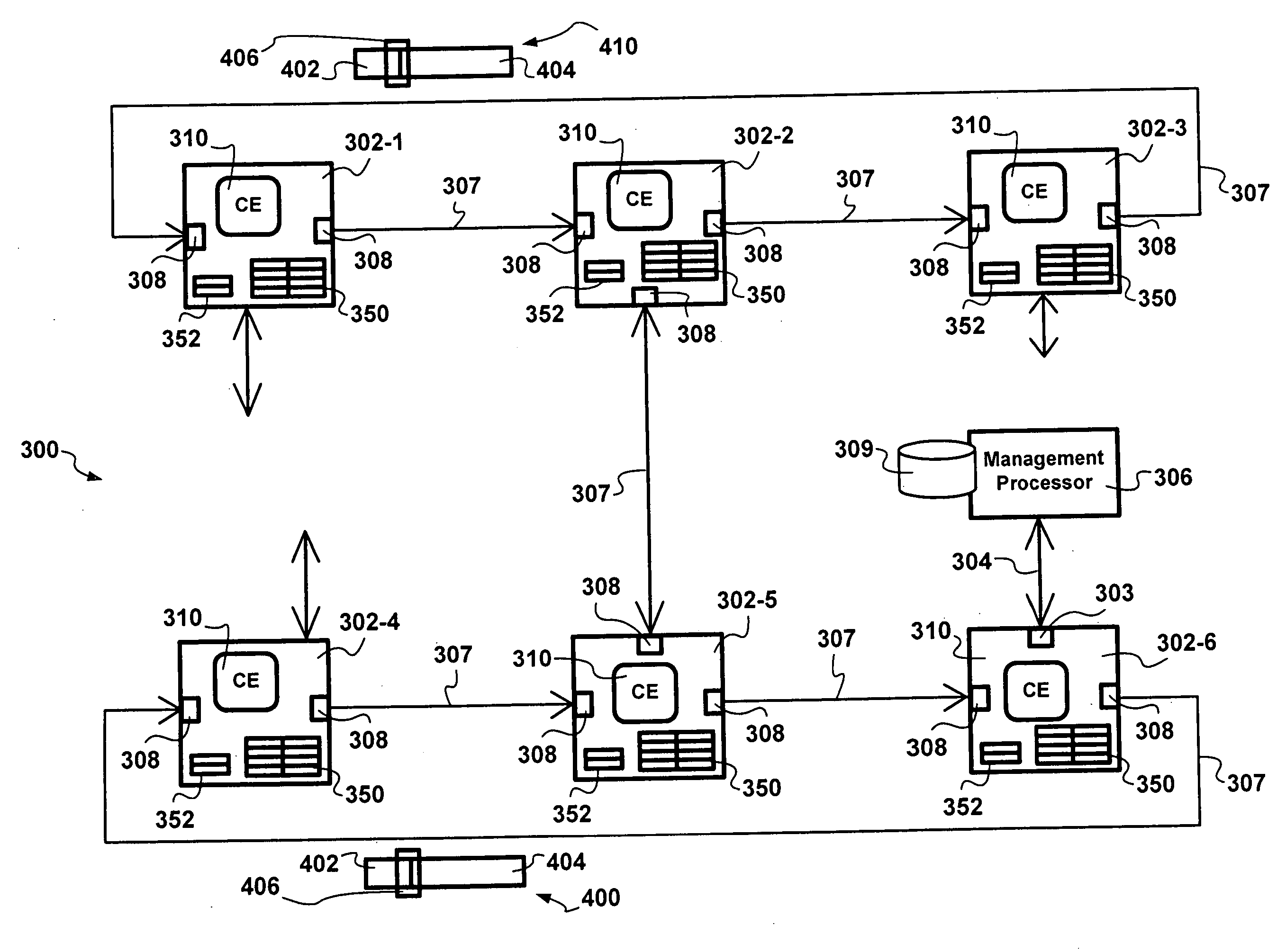
[0028] Making reference to FIG. 3, in accordance with an exemplary embodiment of the invention, network switches 302 in a stack 300 are configured and controlled by a management processor 306 connected 304 to one of the switching network nodes 302 without deploying a separate management processor for each switching network node 302 in the stack 300. The approach presented herein is referred to as a remote configuration and control of switching nodes 302 in a stack 300.

[0029] Exemplary elements of a remote configuration and control deployment in a stacking configuration include links interconnecting switching nodes 302 referred to as stacking links 307 connecting stacking ports 308.

[0030] In accordance with the exemplary embodiment of the invention, each frame 400 transmitted from via a stacking port 308 includes a Frame stacking TAG (FTAG) 406, having the following exemplary format:

FieldField DescriptionClassifier action0 - Normal L2 / L3 search.1 - Flow-based table lookup. Use fl...


PUM


Abstract

A methods and apparatus for remote management of switching network nodes in a stack via in-band messaging are presented. Switching nodes in the stack default to reserved switching node identifiers and stacking ports default to a blocking state upon startup, restart, and reset. Each command frame received via a blocking state is forwarded to a command engine at each switching node and is acknowledged with the current switching node identifier. Each acknowledgement frame bearing the reserved network node identifier triggers configuration of the acknowledging switching node. Switching nodes and the management processor track interrupt state vectors regarding events. An interrupt acknowledgement process is employed to track raised interrupts. Configuration of switching node is performed via command frames transmitted by the management processor and destined to a command engine associated with the switching node. Services provided by the management processor are requested via control frames destined to the switching node to which the management processor is attached and destined to the management port thereof. The advantages are derived from engineered switching node deployments wherein an appropriate number of management processors, less than the number of switching nodes in the stack, are employed to provide services to corresponding switching nodes in the stack, based on processing, control, and configuration bandwidth requirements. The in-band configuration and control of the switching nodes in the stack reduce deployment, configuration, management, and maintenance overheads.

Description

FIELD OF THE INVENTION [0001] The invention relates to switching network node control in communication networks, and in particular to methods of controlling multiple switching network nodes in a stack, wherein only a few switching network nodes in the stack have a management processor attached thereto. BACKGROUND OF THE INVENTION [0002] In the field of packet-switched communications, switching network nodes are employed to direct packet traffic to appropriate network destinations. Switching network nodes may operate in a managed mode in which the switching node employs the services of a management processor, or may operate in an unmanaged mode in which the switching node operates on its own. Both modes of operation are desired as in the managed mode the management processor provides, for example, learning functionality for the switching node, while the related management overhead is not incurred in the unmanaged mode. During normal operation, main sources of traffic to and from the ...

Claims


Application Information

Patent Timeline
Patent Type & Authority Applications(United States)
IPC IPC(8): H04L12/28H04L45/28
CPCH04L41/0803H04L49/65H04L49/557H04L49/555H04L2012/5603
Inventor CHANG, RONG-FENGTWU, MIKEBARRACK, CRAIGYU, ALLEN
Owner SYNAPTICS INC
Why Eureka
Try Eureka