
Motion estimation and compensation device with motion vector correction based on vertical component values

Inactive Publication Date: 2006-02-02
FUJITSU MICROELECTRONICS LTD
View PDF1 Cites 110 Cited by
  • Summary
  • Abstract
  • Description
  • Claims
  • Application Information

AI Technical Summary

Benefits of technology

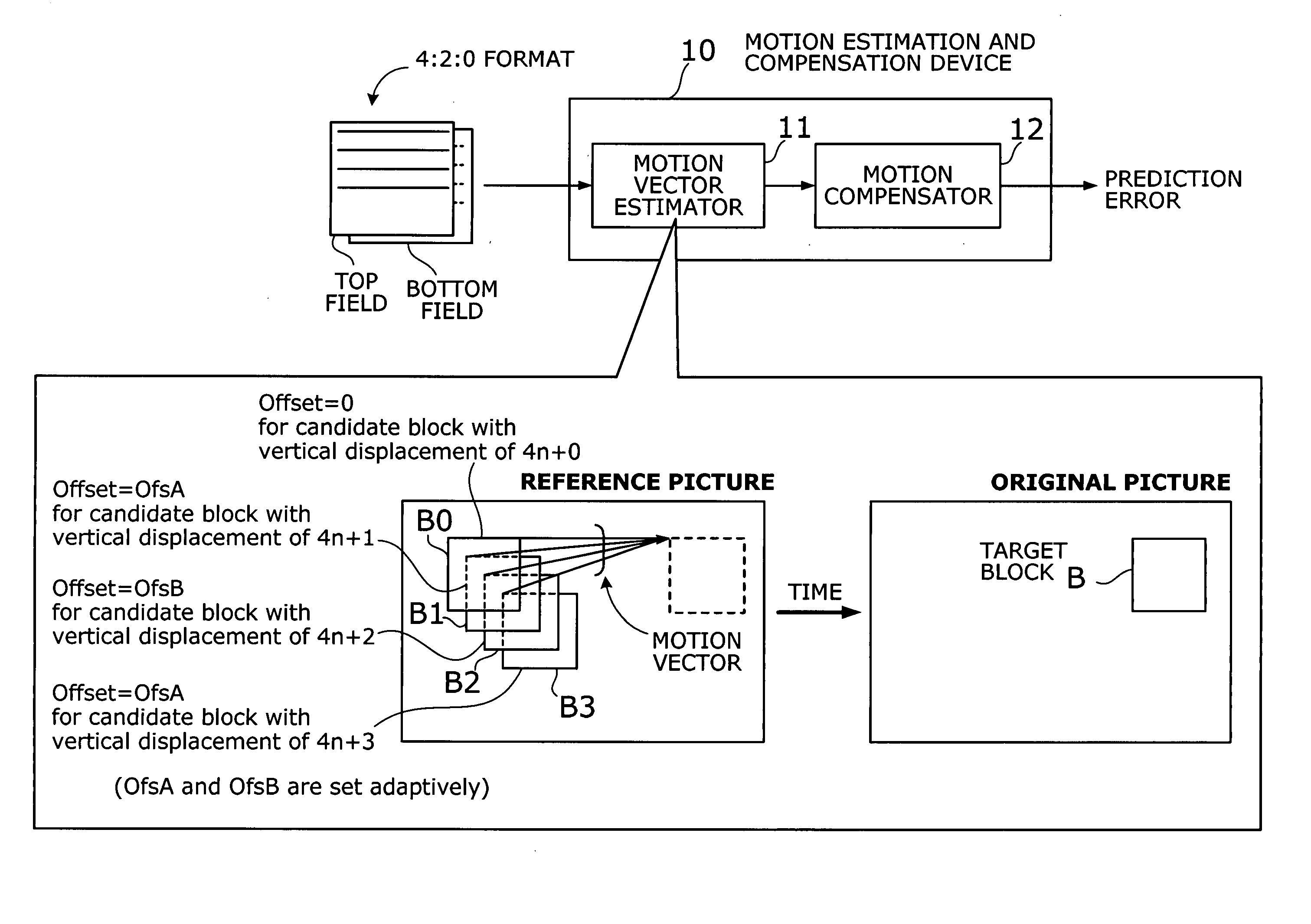
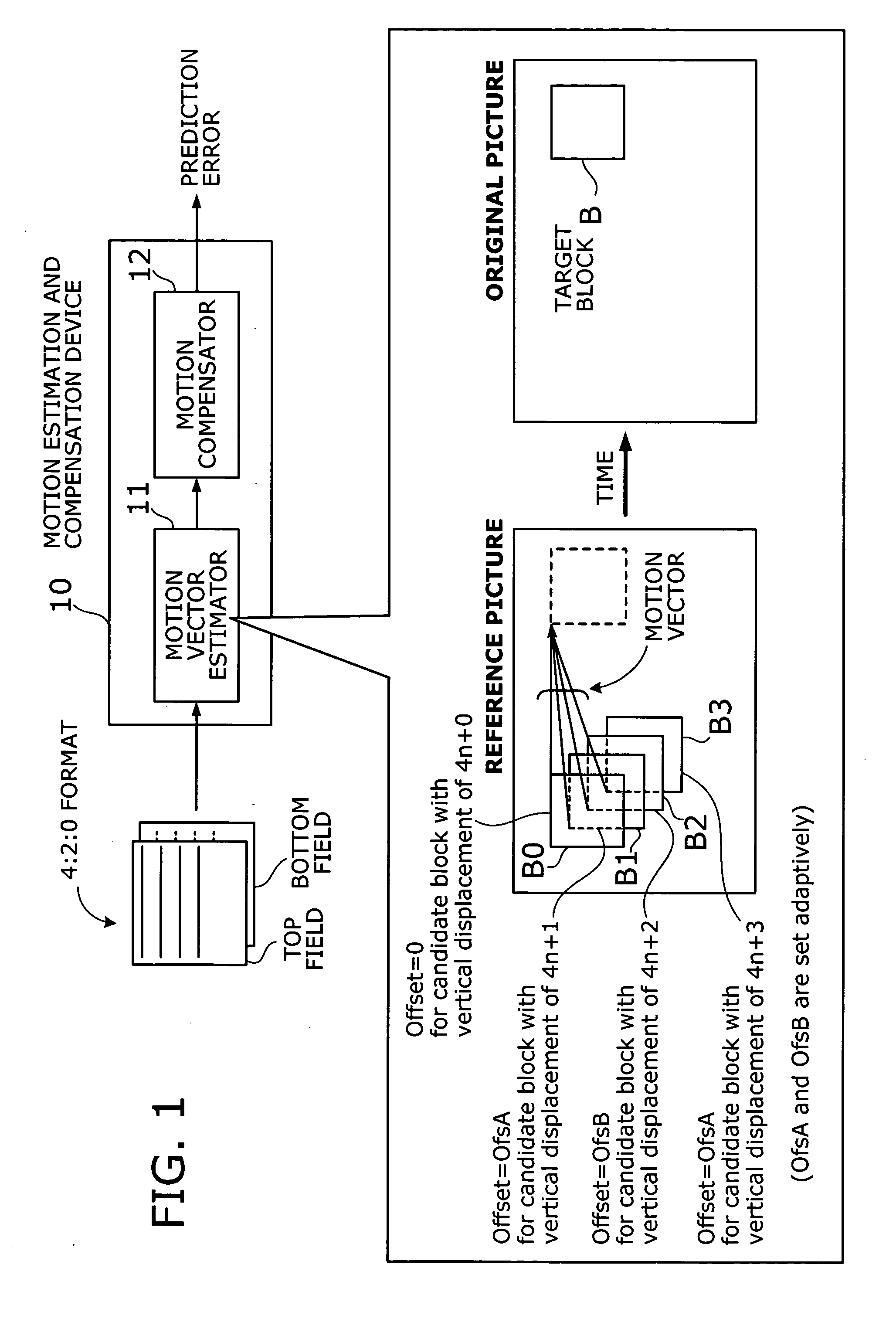
[0018] The present invention provides a motion estimation and compensation device for estimating motion vectors and performing motion-compensated prediction. This motion estimation and compensation device has a motion vector estimator and a motion compensator. The motion vector estimator estimates motion vectors representing motion in given interlace-scanning chrominance-subsampled video signals. The estimation is accomplished by comparing each candidate block in a reference picture with a target block in an original picture by using a sum of absolute differences (SAD) in luminance as similarity metric, choosing a best matching candidate block that minimizes the SAD, and determining displacement of the best matching candidate block relative to the target block. In this process, the motion vector estimator gives the SAD of each candidate block an offset determined from the vertical component of a candidate motion vector associated with that candidate block. With this motion vector correction, the estimated motion vectors are less likely to cause discrepancies in chrominance components. The motion compensator produces a predicted picture using such motion vectors and calculates prediction error by subtracting the predicted picture from the original picture.

Problems solved by technology

On the other hand, if the moving object is, for example, a flying bird, there will be some amount of error between a predicted picture and an original picture since the bird changes the angle and shape of its wings while flying in the air.

Method used


Image

  • Motion estimation and compensation device with motion vector correction based on vertical component values
  • Motion estimation and compensation device with motion vector correction based on vertical component values
  • Motion estimation and compensation device with motion vector correction based on vertical component values

Examples


second embodiment

[0129] This section describes a second embodiment of the present invention. To avoid the problem of chrominance discrepancies, the first embodiment adds appropriate offsets, e.g., OfsA and OfsB, to SAD values corresponding to candidate motion vectors with a vertical component of 4n+1, 4n+3, or 4n+2, thus reducing the chance for those vectors to be picked up as a best match. The second embodiment, on the other hand, takes a different approach to solve the same problem. That is, the second embodiment avoids chrominance discrepancies by adaptively switching between frame prediction mode and field prediction mode, rather than biasing the SAD metric with offsets.

[0130]FIG. 41 shows a conceptual view of the second embodiment. The illustrated motion detection and compensation device 20 has a motion vector estimator 21 and a motion compensator 22. The motion vector estimator 21 estimates motion vectors using luminance components of an interlaced sequence of chrominance-subsampled video sig...


PUM


Abstract

A motion estimation and compensation device that avoids discrepancies in chrominance components which could be introduced in the process of motion vector estimation. The device has a motion vector estimator for finding motion vectors in given interlace-scanning chrominance-subsampled video signals. The estimator compares each candidate block in a reference picture with a target block in an original picture by using a sum of absolute differences (SAD) in luminance as similarity metric, chooses a best matching candidate block that minimizes the SAD, and determines its displacement relative to the target block. In this process, the estimator gives the SAD of each candidate block an offset determined from the vertical component of a corresponding motion vector, so as to avoid chrominance discrepancies. A motion compensator then produces a predicted picture using such motion vectors and calculates prediction error by subtracting the predicted picture from the original picture.

Description

CROSS-REFERENCE TO RELATED APPLICATIONS [0001] This application is based upon and claims the benefits of priority from the prior Japanese Patent Application No. 2004-219083, filed on Jul. 27, 2004, the entire contents of which are incorporated herein by reference. BACKGROUND OF THE INVENTION [0002] 1. Field of the Invention [0003] The present invention relates to a motion estimation and compensation device, and more particularly to a motion estimation and compensation device that estimates motion vectors and performs motion-compensated prediction of an interlaced sequence of chrominance-subsampled video frames. [0004] 2. Description of the Related Art [0005] Digital compression and coding standards of the Moving Picture Experts Group (MPEG) are widely used today in the fields of, for example, DVD videos and digital TV broadcasting to record or transmit large amounts of motion image data at a high quality. MPEG standards require the use of YCbCr color coding scheme, which represents ...

Claims


Application Information

Patent Timeline
IPC IPC(8): H04N11/02H04N11/04H04N7/12H04B1/66G06T7/20H04N19/105H04N19/134H04N19/176H04N19/186H04N19/196H04N19/50H04N19/503H04N19/51H04N19/513H04N19/59H04N19/61H04N19/625H04N19/85H04N19/91
CPCH04N19/56H04N19/186H04N19/112H04N19/51
Inventor OTSUKA, TATSUSHITAHIRA, TAKAHIKOYAMORI, AKIHIRO
Owner FUJITSU MICROELECTRONICS LTD
Learn More