
Image encoding apparatus and method, computer program, computer-readable storage medium, and image forming apparatus

a technology of image data and encoding apparatus, applied in the direction of electrical apparatus, instruments, computing, etc., can solve the problems of document reading at least two times at poor efficiency, memory overflow, and difficulty in encoding image data within the target code amount without prescan, and achieve the effect of efficient encoding of input images

Inactive Publication Date: 2006-02-02
CANON KK
View PDF46 Cites 37 Cited by
  • Summary
  • Abstract
  • Description
  • Claims
  • Application Information

AI Technical Summary

Benefits of technology

[0010] The present invention has been made in consideration of the above situation, and has as its object to provide a technique of efficiently encoding an input image in accordance with its property while generating encoded data of a target code amount or less by one image input operation.

Problems solved by technology

According to JPEG encoding as an internal standardization scheme, only one quantization matrix can be defined for an image, and it is difficult to make image data fall within a target code amount without prescan.
When JPEG encoding is used in a system which stores data in a limited memory, a memory overflow may occur.
As described above, prescan and actual scan are generally executed, but a document must be read at least two times at poor efficiency.
However, a compression process corresponding to area information of an image does not always provide a high-quality decoded image based on the compression-encoded result.
This is because area determination is not always correct.
Further, when a normal document deteriorates over time or becomes dirty and loses its contrast, the document may be mistaken as a photo or the like.

Method used


Image

  • Image encoding apparatus and method, computer program, computer-readable storage medium, and image forming apparatus
  • Image encoding apparatus and method, computer program, computer-readable storage medium, and image forming apparatus
  • Image encoding apparatus and method, computer program, computer-readable storage medium, and image forming apparatus

Examples


first embodiment

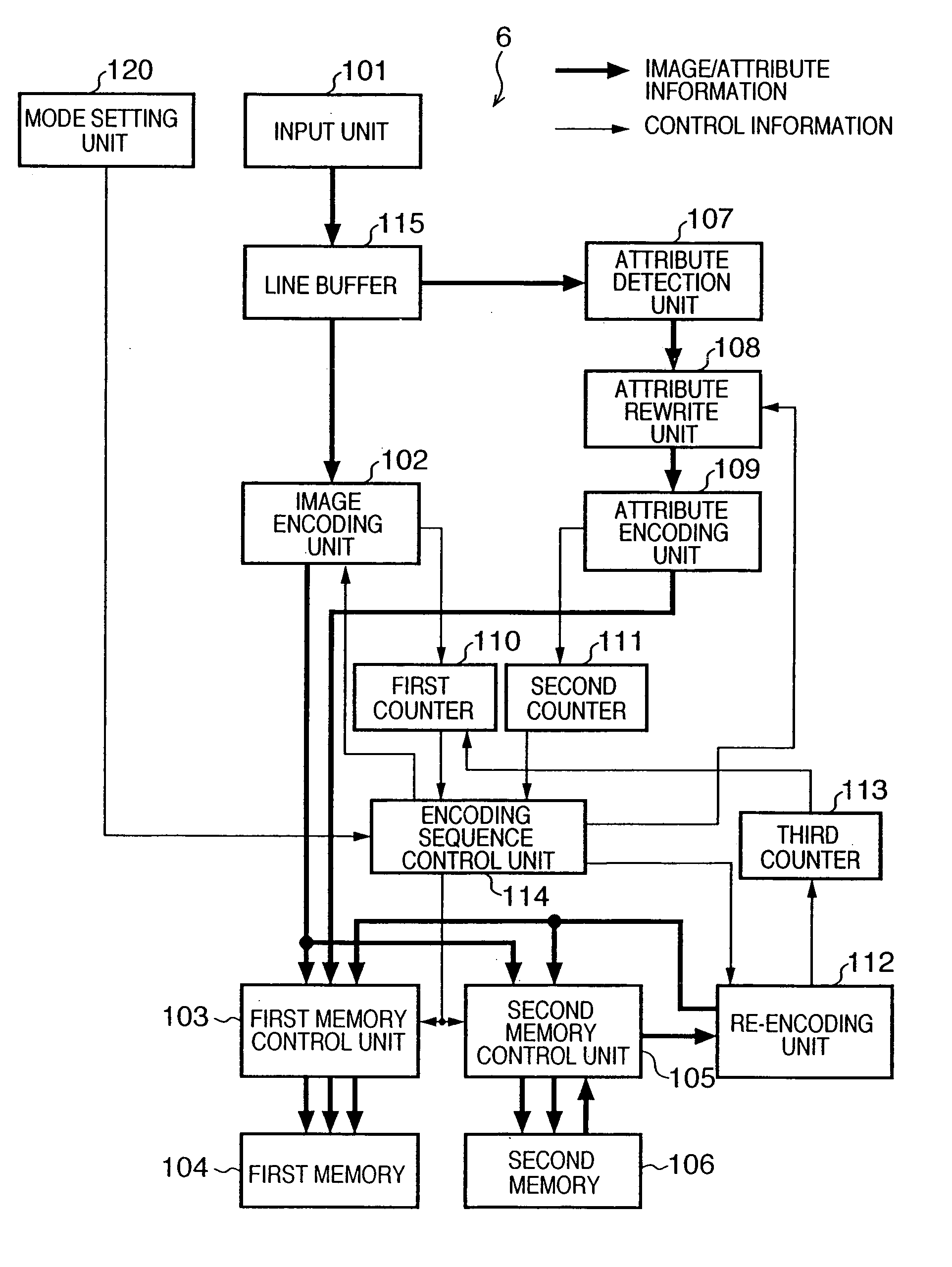
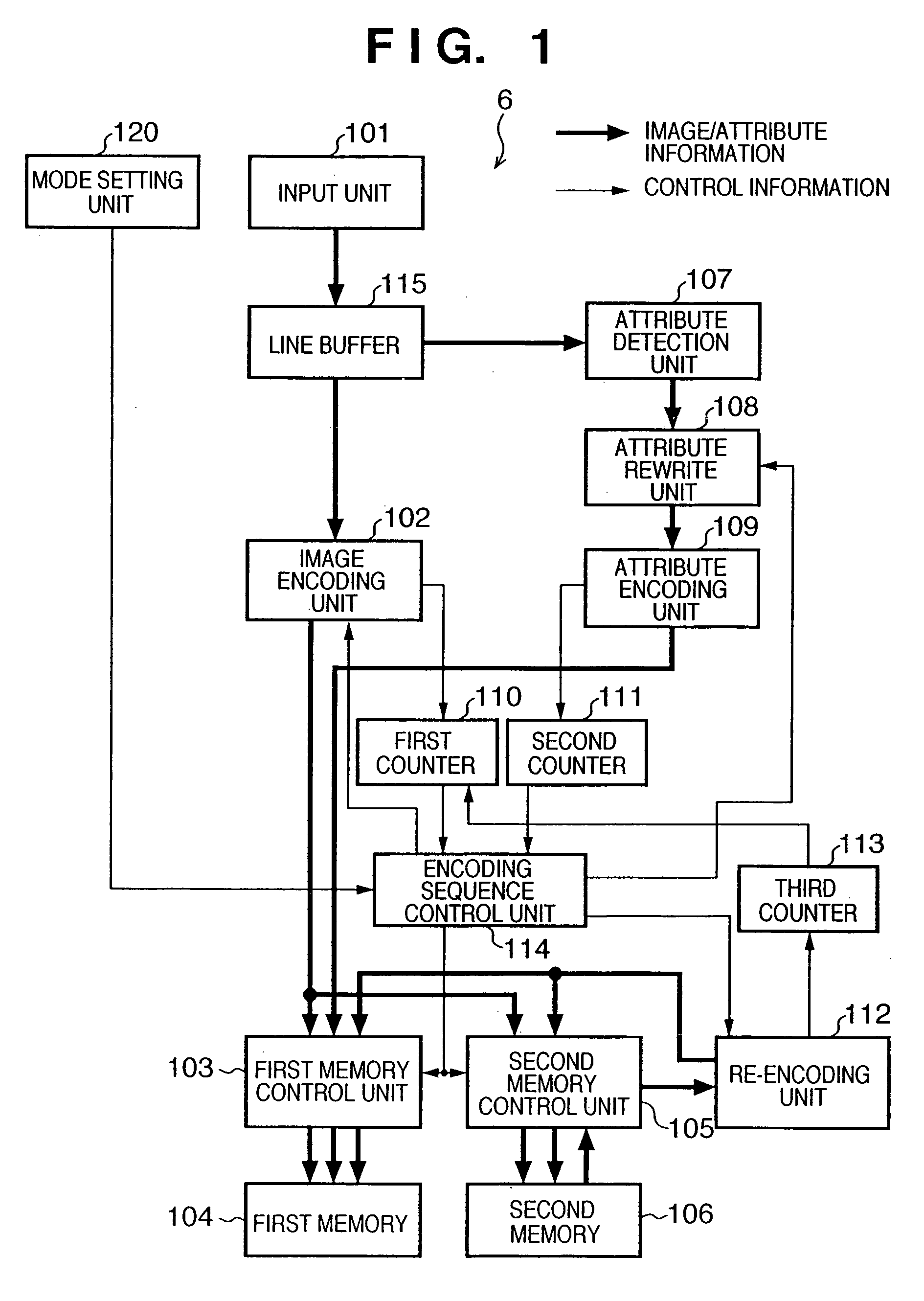
[0067]FIG. 1 is a block diagram showing an encoding unit 6 according to the first embodiment. Each unit in FIG. 1 will be briefly explained.

[0068] As described above, an input unit 101 receives image data from a document reading unit 3 or rendering unit 4 via a selector 5, and outputs the image data to a line buffer 115. The line buffer has a capacity corresponding to a plurality of lines.

[0069] An image encoding unit 102 encodes image data stored in the line buffer 115, and stores the encoded data in a first memory 104 and second memory 106 via a first memory control unit 103 and second memory control unit 105.

[0070] The image encoding unit 102 according to the first embodiment adopts JPEG encoding (lossy encoding). More specifically, image data corresponding to 8×8 pixels is orthogonally transformed, quantized using a quantization step (to be described later), and undergoes a Huffman encoding process. The quantization step determines a generated code amount, and is set by an en...

second embodiment

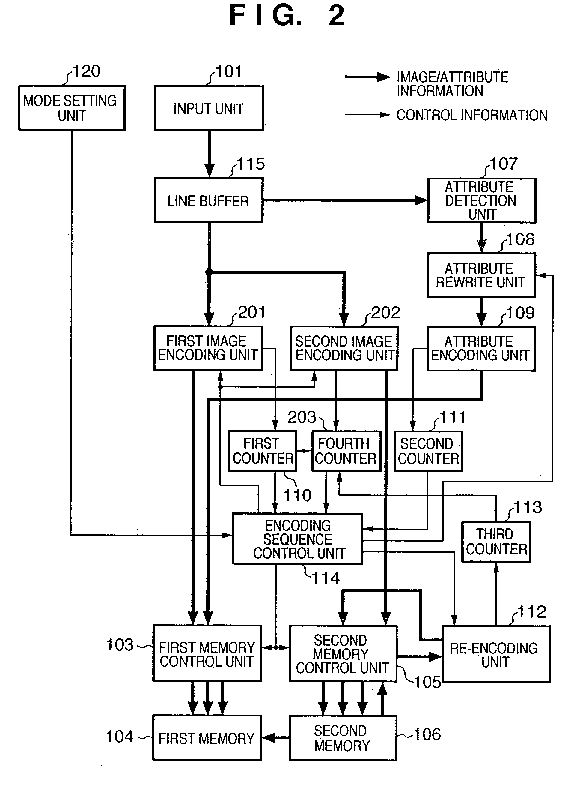
[0140] The second embodiment according to the present invention will be described. The arrangement of an encoding unit 6 according to the second embodiment is shown in FIG. 2.

[0141] In FIG. 1, a processing unit which encodes an image is only one image encoding unit 102. To the contrary, in FIG. 2, two, first and second image encoding units 201 and 202 are arranged, these two encoding units parallel-execute an encoding process. Further, a fourth counter 203 is arranged which cumulatively counts an encoded data length generated by the second image encoding unit 202.

[0142] The first and second image encoding units 201 and 202 in the second embodiment perform JPEG encoding, similar to the image encoding unit 102 in the first embodiment.

[0143] An outline of a process in the arrangement of FIG. 2 will be explained.

[0144] Encoded data output from the first image encoding unit 201 is stored in a first memory 104 via a first memory control unit 103. At this time, a first counter 110 cumu...


PUM


Abstract

According to this invention, the encoded data amount of an image and its area attribute information can be encoded to a target amount or less by one input operation of image data, and an input image can be efficiently encoded in accordance with the property of the image. For this purpose, an encoding sequence unit sets an initial quantization matrix table for an image encoding unit in accordance with a mode set by a mode setting unit, and sets parameters associated with attribute rewrite for an attribute rewrite unit. When an image is input, encoded image data generated by the image encoding unit is stored in a memory. Attribute-encoded data generated by an attribute encoding unit is also stored in the memory. The first counter counts an encoded-image data amount, and the second counter counts an attribute-encoded data amount. When the sum of these encoded data exceeds a target amount, the encoding sequence control unit updates the quantization matrix table for the image encoding unit, and causes the image encoding unit to continue encoding. The updated quantization matrix table is set for a re-encoding unit, and encoded data stored in the memory is re-encoded.

Description

FIELD OF THE INVENTION [0001] The present invention relates to an image data compression encoding technique. BACKGROUND OF THE INVENTION [0002] Conventionally, still image data is often compressed by a method using discrete cosine transform or a method using Wavelet transform. Encoding of this type is variable-length encoding, and hence the code amount changes for each image to be encoded. [0003] According to JPEG encoding as an internal standardization scheme, only one quantization matrix can be defined for an image, and it is difficult to make image data fall within a target code amount without prescan. When JPEG encoding is used in a system which stores data in a limited memory, a memory overflow may occur. [0004] In order to prevent this, conventional schemes used, for example, a method of re-reading a document upon changing the compression ratio parameter when the actual code amount exceeds an expected code amount, or a method of estimating a code amount in advance by prescan a...

Claims


Application Information

Patent Timeline
IPC IPC(8): G06K9/36H04N1/413H04N19/00H04N19/115H04N19/126H04N19/146H04N19/196H04N19/40H04N19/463H04N19/625H04N19/70H04N19/91
CPCH04N19/172H04N19/46H04N19/152H04N19/124H04N19/60
Inventor ITO, NAOKI
Owner CANON KK
Learn More