Camera

Inactive Publication Date: 2006-02-02
CANON KK
View PDF8 Cites 3 Cited by
  • Summary
  • Abstract
  • Description
  • Claims
  • Application Information

AI Technical Summary

Benefits of technology

[0013] An object of the present invention is to provide a camera to which

Problems solved by technology

As a result, it becomes necessary to form a built-in electric circuit board having a shape for preventing the interference to the exterior member, thereby impeding the miniaturization of the camera and

Method used


Image

  • Camera
  • Camera
  • Camera

Examples


Embodiment Construction

[0022] Preferred embodiments of the present invention will hereinafter be described with reference to the drawings.

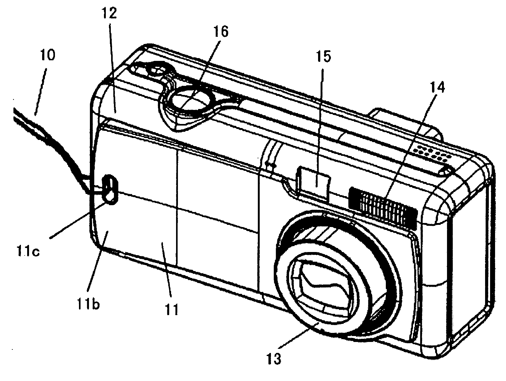
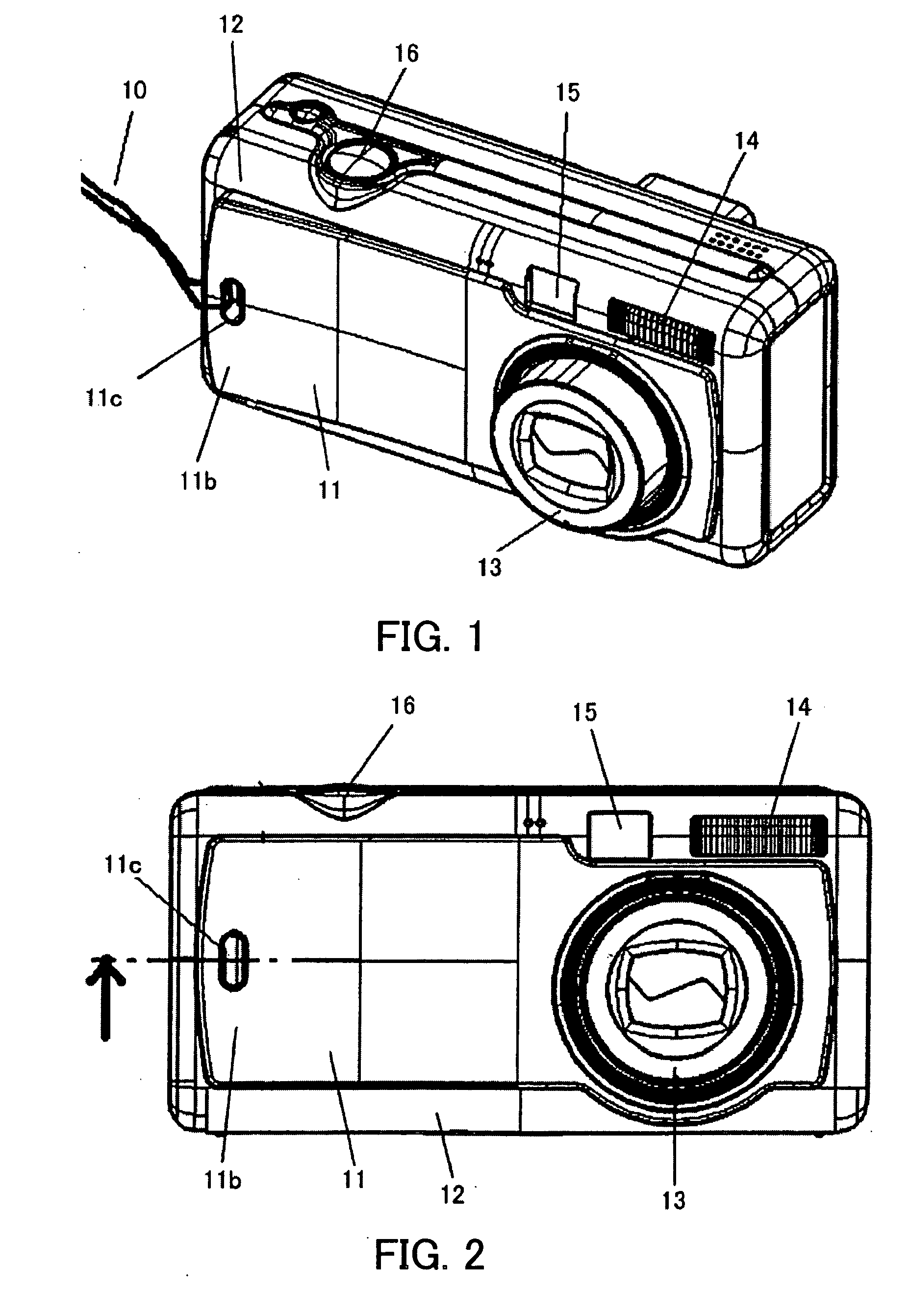
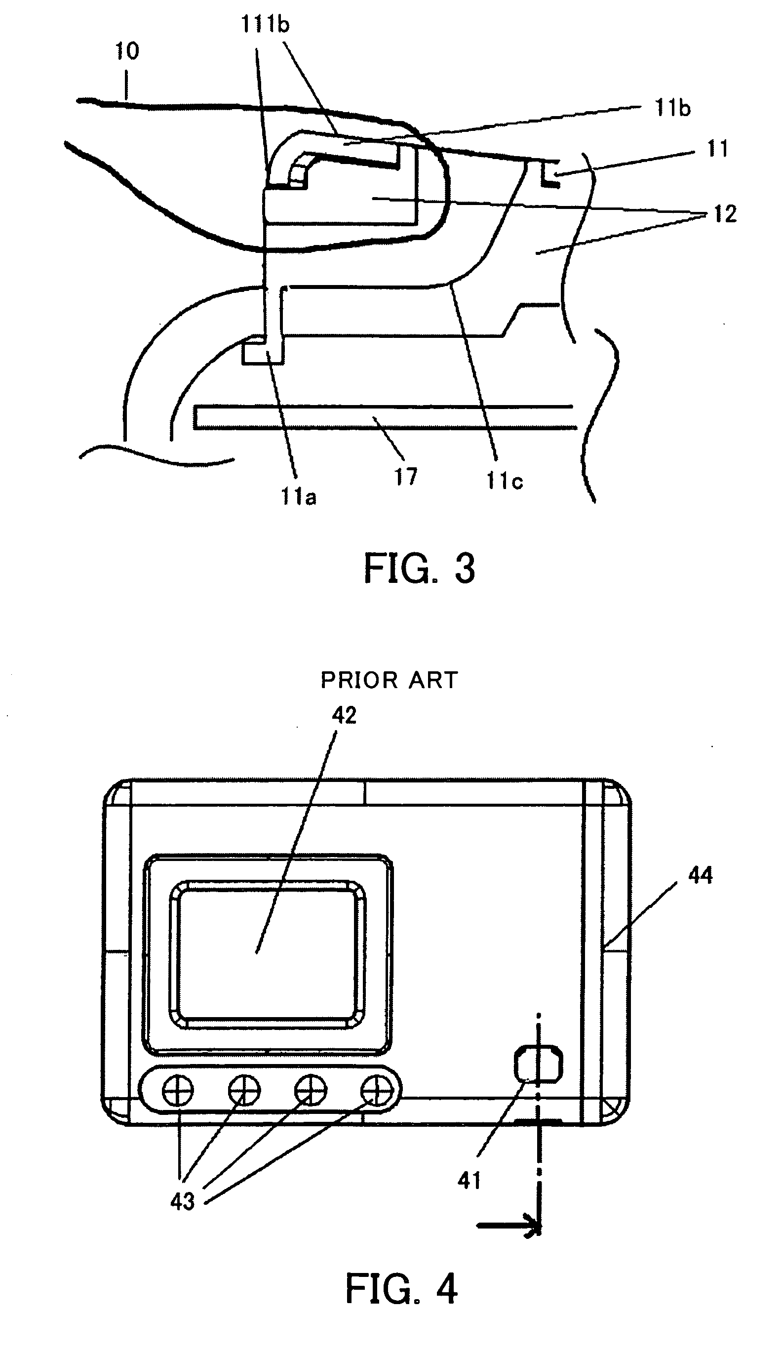
[0023] FIGS. 1 to 3 shows a digital camera which is an embodiment of the present invention. FIG. 1 is a perspective view of the digital camera, FIG. 2 is a front view of the digital camera, and FIG. 3 is a sectional view of a strap-attachment portion in the embodiment.

[0024] In FIG. 1, reference numeral 10 denotes a strap that is attached to the after-mentioned strap-opening portion 11c. Putting a photographer's wrist through the strap 10 prevents the camera from dropping on the ground.

[0025] Reference numeral 11 denotes a first front exterior member (first exterior member) constituting the exterior of the camera. On the backside of the first front exterior member 11, an engaging protrusion 11a having a hook-like shape is formed. The engaging protrusion 11a engages with the back surface of a second front exterior member (second exterior member) 12.

[0026] The first f...


PUM


Abstract

A camera is disclosed, to which a strap can be attached without reducing the space inside the camera body. The camera comprises a first exterior member, which constitutes an object side surface of a camera body. A first area of the first exterior member protrudes with respect to other areas of the first exterior member to constitute a grip portion. An attachment portion to which the strap is attached is provided in the first area.

Description


Claims


Application Information

Patent Timeline
Owner CANON KK
Why Eureka
Try Eureka