Inversion of scan clock for scan cells

a scan cell and clock technology, applied in the field of scan cells, can solve the problems of increasing the overhead of dft implementation and increasing the cost of die and testing

Active Publication Date: 2006-02-02
MARVELL ASIA PTE LTD
View PDF17 Cites 48 Cited by
  • Summary
  • Abstract
  • Description
  • Claims
  • Application Information

AI Technical Summary

Problems solved by technology

This in turn may increase DFT implementation o

Method used


Image

  • Inversion of scan clock for scan cells
  • Inversion of scan clock for scan cells
  • Inversion of scan clock for scan cells

Examples


Embodiment Construction

[0022] In the following description, for purposes of explanation, numerous details are set forth in order to provide a thorough understanding of the disclosed embodiments of the present invention. However, it will be apparent to one skilled in the art that these specific details are not required in order to practice the disclosed embodiments of the present invention. In other instances, well-known electrical structures and circuits are shown in block diagram form in order not to obscure the disclosed embodiments of the present invention.

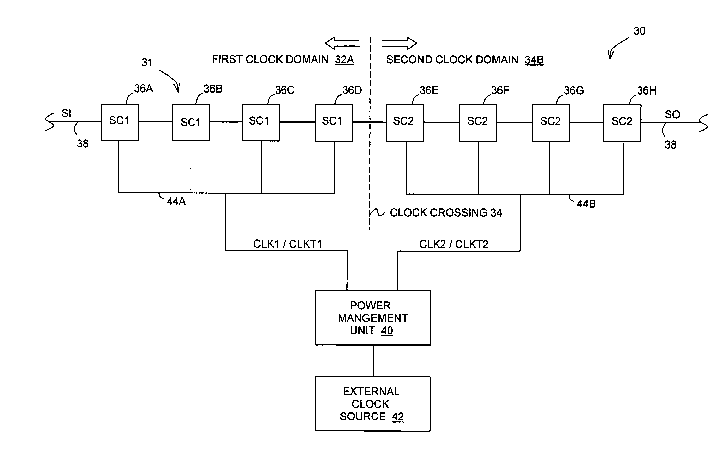
[0023] With reference to FIG. 3, there is illustrated an integrated circuit (IC) chip 30 having a plurality of clock domains 32, with two such clock domains being illustrated by the first clock domain 32A and the second clock domain 32B. The interface of the illustrative clock domains 32A and 32B is shown by a clock crossing 34. The IC chip 30 may include scan circuit 31 which includes a plurality of scan cells 36 (illustrated by scan cells 36A-H) w...


PUM


Abstract

In one embodiment, an apparatus comprises a scan circuit including at least a first and a second clock domain and a scan chain having a first plurality of scan cells positioned in the first clock domain and a second plurality of scan cells positioned in the second clock domain. A scan clock source, coupled to the scan chain, generates a first scan clock signal to the first plurality of scan cells and a second scan clock signal to the second plurality of scan cells. The first and the second clock signals have an inverted relationship.

Description

BACKGROUND [0001] 1. Technical Field [0002] Embodiments of the present invention are related to the field of electronic devices, and in particular, to scan cells. [0003] 2. Description of Related Art [0004] A typical integrated circuit (IC) chip has combination logic circuits which are coupled by flip-flops or latches controlled by a plurality of clock signals, with the combination logic circuits and latches utilizing a particular clock signal defining one of a plurality of functional clock domains. For example, in one illustrative IC chip, there are more than 30 different internal functional clock domains with frequency ranging from 1 KHz to 312 MHz. [0005] Referring to FIG. 1, Design-For-Testability (DFT) mechanisms for an IC chip 10 include utilizing a plurality of scan cells 12 to perform manufacturing tests on the IC chip 10. In one scan cell design, sometimes referred to as a “mux flip-flop”, each scan cell 12 has a flip-flop 14, such as a D-flip-flop, and a multiplexer 16. Ea...

Claims


Application Information

Patent Timeline
IPC IPC(8): G01R31/28
CPCG01R31/318594G01R31/318541
Inventor PATRICK TAN, TECK WEE
Owner MARVELL ASIA PTE LTD
Why Eureka
Try Eureka