Systems for detecting electrical faults in a vehicle

a technology for electrical systems and vehicles, applied in the direction of fault location by conductor types, instruments, measurement devices, etc., can solve the problems of dangerous vehicle operation, significant vibration of vehicles, and wear of wiring and other interconnections of vehicles

Active Publication Date: 2016-07-14
GE GLOBAL SOURCING LLC
View PDF1 Cites 17 Cited by
  • Summary
  • Abstract
  • Description
  • Claims
  • Application Information

AI Technical Summary

Benefits of technology

[0009]In an embodiment, a system (e.g., an electrical fault location detection system) includes a control unit for a vehicle and a plurality of scan circuits in the vehicle. The control unit is configured to electrically couple the plurality of scan circuits to an electrical system of the vehicle. The control unit is further configured to trigger the plurality of scan circuits to respectively pass a plurality of electrical signals to the electrical system of the vehicle. Respective scan circuits of the plurality of scan circuits are respectively configured to detect a presence of an electrical fault in the electrical system based on respective electrical signals of the plurality of electrical signals. The respective scan circuits are further configured to provide information indicative of a location of the electrical fault in the electrical system, when detected, to the control unit.
[0010]In an embodiment, a system (e.g., an electrical fault location detection system) includes a fault location unit/s

Problems solved by technology

Modern vehicles include complex control systems and power systems that involve multiple components dispersed throughout the vehicle and extensive wiring interconnecting the components.
In operation, a vehicle can experience significant vibration.
Over time, wiring and other interconnections of the vehicle can exhibit signs of wear due to reoccurring stresses associated with regular operation.
Deterioration of the wiring can introduce faults that prevent proper operation of the vehicle, or can lead to une

Method used


Image

  • Systems for detecting electrical faults in a vehicle
  • Systems for detecting electrical faults in a vehicle
  • Systems for detecting electrical faults in a vehicle

Examples


Embodiment Construction

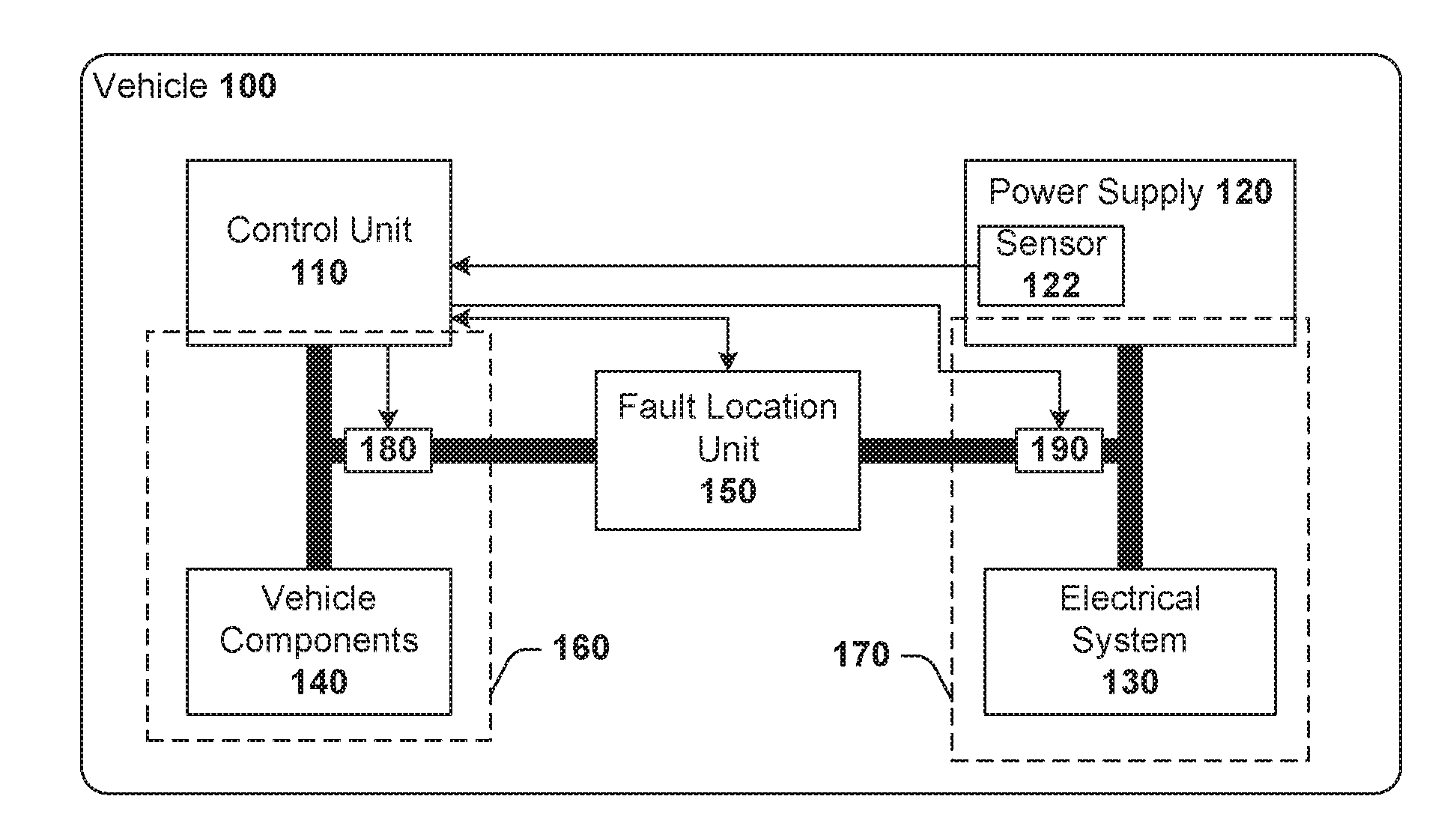
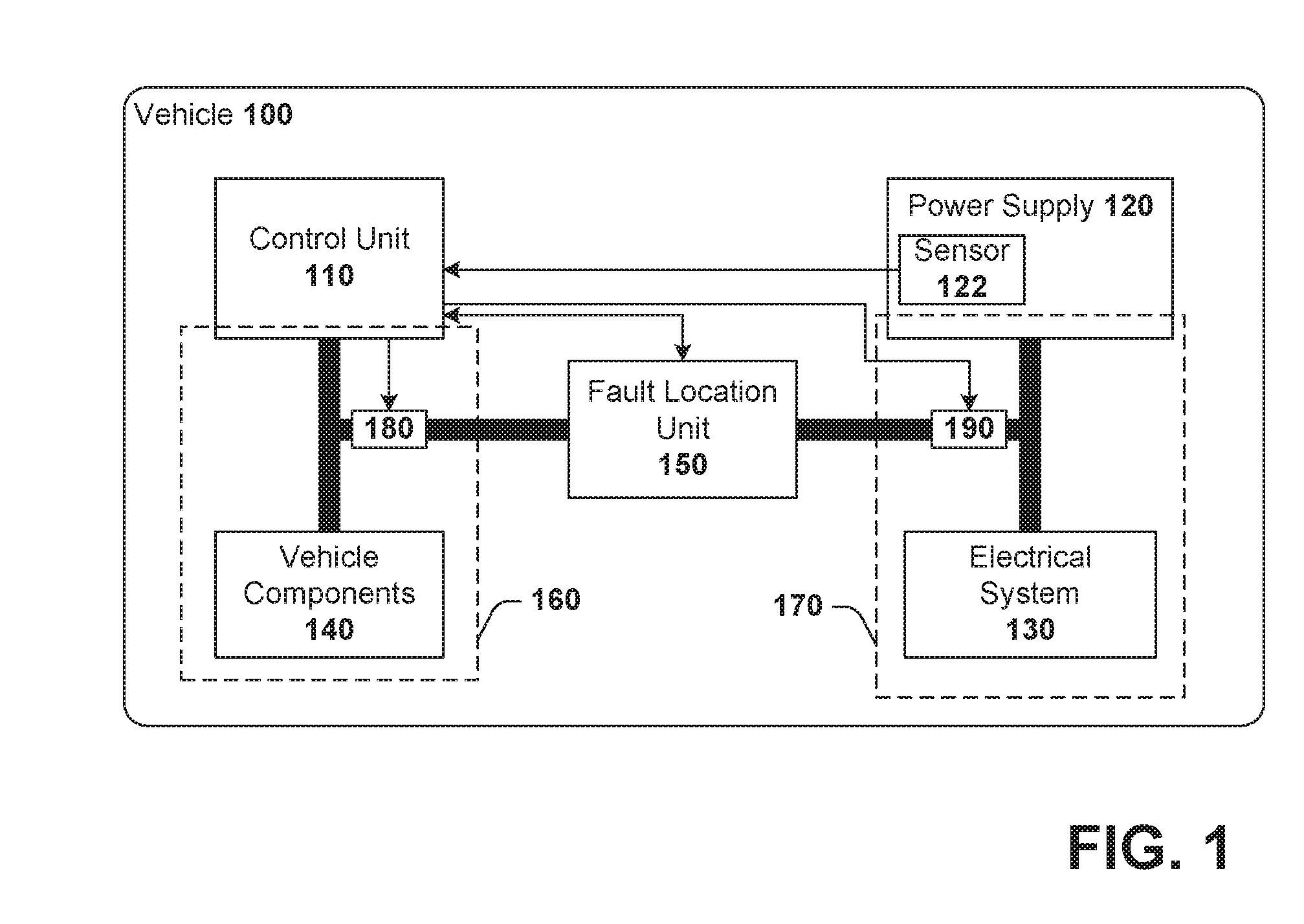
[0025]Embodiments described herein generally relate to systems and methods for locating an electrical fault in an electrical system of a vehicle. The vehicle can include an extensive amount of wiring running throughout. In addition to the wiring, the vehicle can also include numerous electrical interconnections, control lines, electrical devices, and / or other electronic devices that can be further a cause of the electrical fault. Conventionally, narrowing down a location of the electrical fault can involve manually testing individual components (e.g., wire, interconnections, device, etc.) separately to pinpoint the culprit. In order to test the components, service personnel generally gain physical access. Accordingly, to merely locate a source of the electrical fault, portions and / or components of the vehicle are disassembled to enable the test.

[0026]Fault locating systems and methods described herein reduce manual and laborious efforts to identify a source of an electrical fault in...


PUM


Abstract

Systems are provided to determine a location of an electrical fault in an electrical system of a vehicle. A test apparatus can include a control unit and a plurality of scan circuits. The control unit is configured to electrically couple the plurality of scan circuits to the electrical system and trigger the plurality of scan circuits to pass electrical signals to the electrical system. Each scan circuit is configured to detect a presence of an electrical fault in the electrical system based on an electrical signal passed. Each scan circuit provides information indicative of a location of the electrical fault in the electrical system, when detected, to the control unit.

Description

CROSS-REFERENCE TO RELATED APPLICATIONS[0001]This application claims priority to U.S. Provisional Application No. 62 / 101,399, filed Jan. 9, 2015, which is hereby incorporated by reference herein in its entirety.BACKGROUND[0002]1. Technical Field[0003]Embodiments of the subject matter disclosed herein relate to detecting electrical faults in an electrical system of a vehicle.[0004]2. Discussion of Art[0005]Modern vehicles include complex control systems and power systems that involve multiple components dispersed throughout the vehicle and extensive wiring interconnecting the components. In operation, a vehicle can experience significant vibration. Over time, wiring and other interconnections of the vehicle can exhibit signs of wear due to reoccurring stresses associated with regular operation. Deterioration of the wiring can introduce faults that prevent proper operation of the vehicle, or can lead to unexpected or unintended, and therefore, dangerous operation of the vehicle.[0006]...

Claims


Application Information

Patent Timeline
IPC IPC(8): G01R31/00G01R31/08
CPCG01R31/08G01R31/005G01R31/007G01R31/086
Inventor COOPER, JARED KLINEMANPELTZ, DAVID MICHAELNAGRODSKY, NICHOLAS DAVIDGOLDEN, SAMUEL WILLIAMSVIDUNOVICH, JEROD REIDHEOB, KEITH ALLENCOPPS, MICHAEL
Owner GE GLOBAL SOURCING LLC
Why Eureka
Try Eureka