Test display module for testing application logic independent of specific user interface platforms

a display module and application logic technology, applied in the field of business software products and applications, can solve the problems of increasing complexity of ui technology, increasing complexity of ui development and maintenance, and increasing the complexity of ui development and maintenance, and the use of such mechanisms is not without significant problems

Inactive Publication Date: 2006-02-02
MICROSOFT TECH LICENSING LLC
View PDF11 Cites 36 Cited by
  • Summary
  • Abstract
  • Description
  • Claims
  • Application Information

AI Technical Summary

Problems solved by technology

Developing and maintaining a large number of forms has traditionally been a labor-intensive task for software developers.
In the near future, personal digital assistant (PDA), cell phone, and other UI technologies will be adding to complexity.
However, use of such mechanisms is not without significant problems.

Method used


Image

  • Test display module for testing application logic independent of specific user interface platforms
  • Test display module for testing application logic independent of specific user interface platforms
  • Test display module for testing application logic independent of specific user interface platforms

Examples


Embodiment Construction

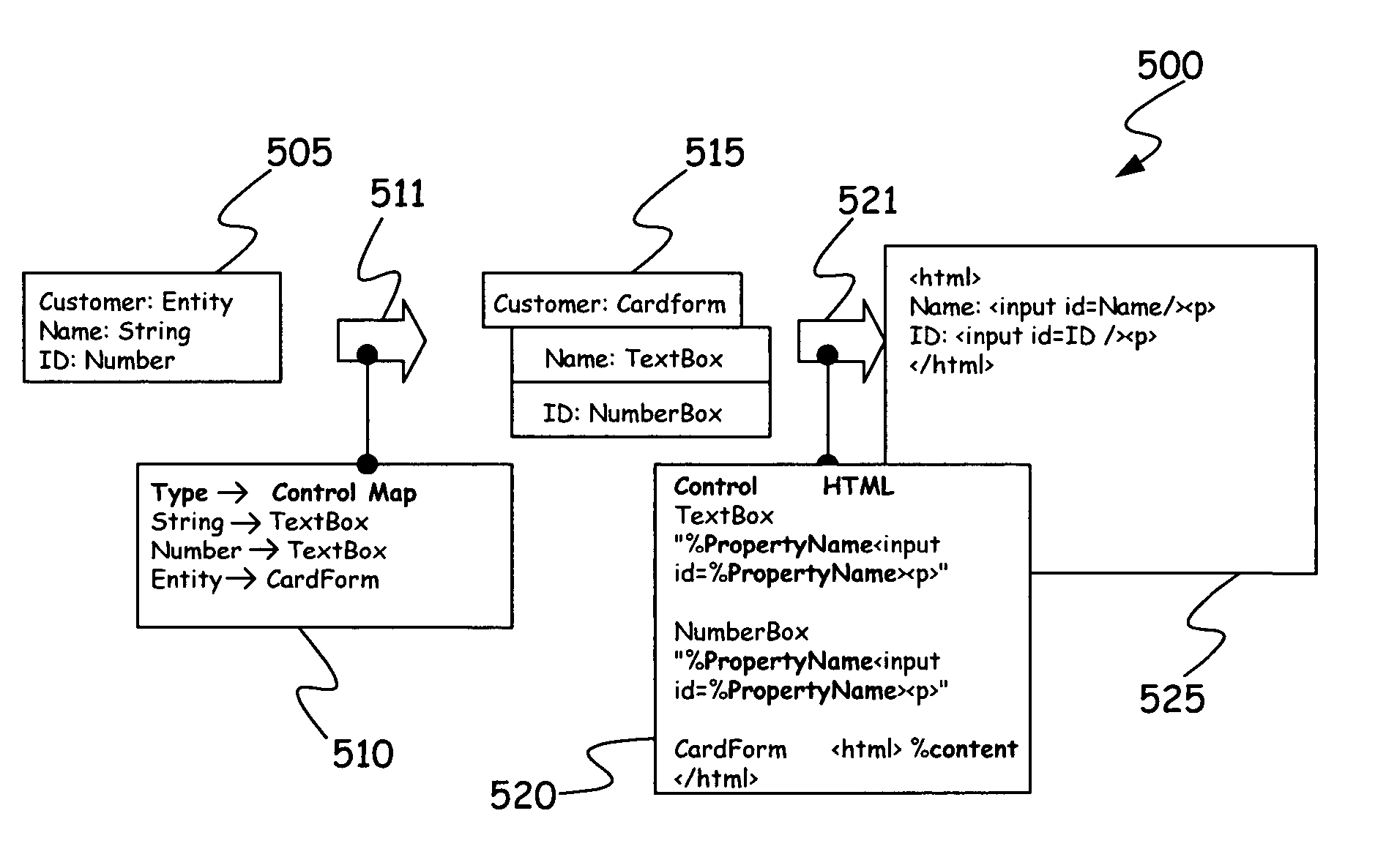
[0025] The present invention relates to a system and method for testing application logic. However, prior to discussing the present invention in greater detail, illustrative environments in which the present invention can be used will be discussed first.

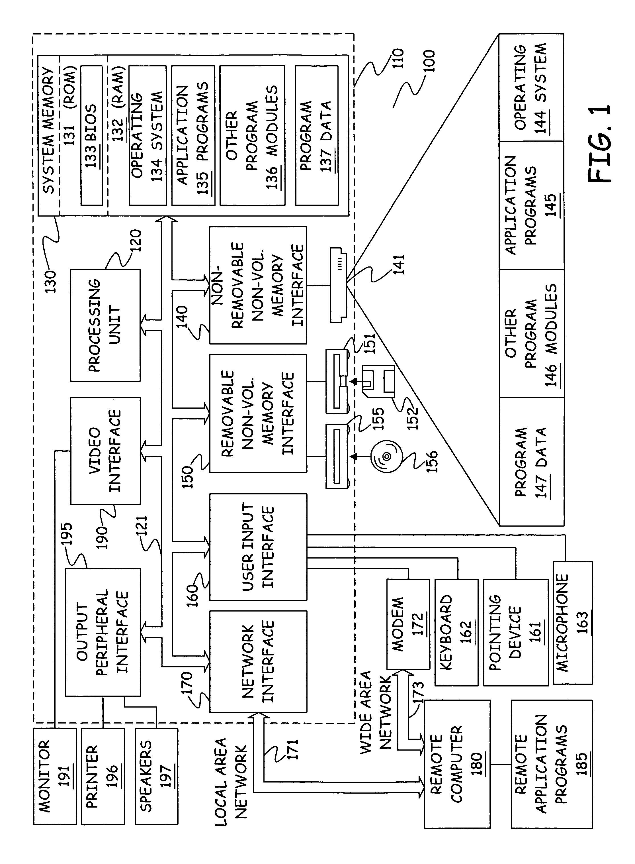
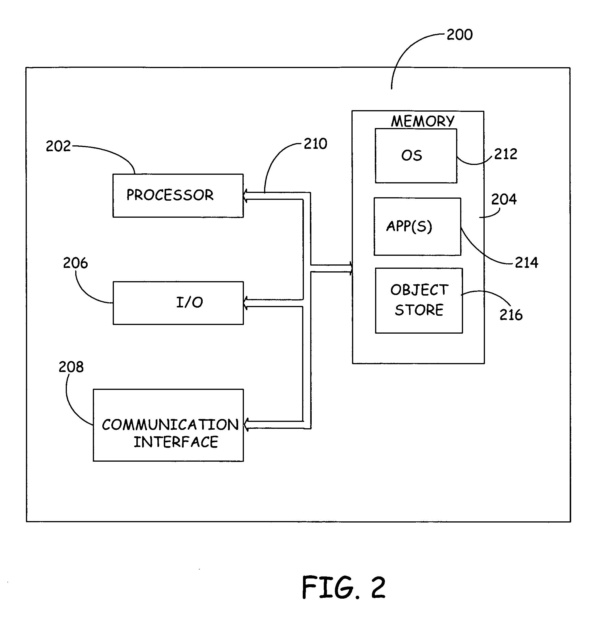
[0026]FIG. 1 illustrates an example of a suitable computing system environment 100 on which the invention may be implemented. FIG. 2 illustrates an example of a mobile device computing environment 200. The computing system environments 100 and 200 are only two examples of suitable computing environments, and are not intended to suggest any limitation as to the scope of use or functionality of the invention. Neither should the computing environments 100 and 200 be interpreted as having any dependency or requirement relating to any one or combination of components illustrated in the exemplary operating environment 100. Description of the methods and apparatus of the present invention with general reference to these computer architectu...


PUM


Abstract

A method, computer readable medium and/or module are provided for testing application logic independent of specific user interface platforms or devices. In the operating environment, an application logic model is provided and is operable with data in a database. A logical layer model is generated having user interface features independent of specific computing devices from data in the database applied to the application logic model. Test data is provided to and data is received from the logical layer model independent (are free from dependencies) of a user interface to test the application logic model. Test scripts can be used to automate the process and provide test data according to a desired sequence or scenario. In another aspect, a recorder is provided to capture data present in or provided to the logical layer model in order to replicate a problem scenario.

Description

CROSS-REFERENCE TO RELATED APPLICATIONS [0001] Reference is hereby made to the following co-pending and commonly assigned patent applications: U.S. application Ser. No. 10 / 860,226, filed Jun. 3, 2004, entitled “METHOD AND APPARATUS FOR GENERATING FORMS USING FORM TYPES”; U.S. application Ser. No. 10 / 860,225, filed Jun. 3, 2004, entitled “METHOD AND APPARATUS FOR MAPPING A DATA MODEL TO A USER INTERFACE MODEL”; and U.S. application Ser. No. 10 / 860,306, filed Jun. 3, 2004, entitled “METHOD AND APPARATUS FOR GENERATING USER INTERFACES BASED UPON AUTOMATION WITH FULL FLEXIBILITY”, all of which are incorporated by reference in their entirety. BACKGROUND OF THE INVENTION [0002] The present invention relates to business software products and applications. More particularly, the present invention relates to methods and apparatus used for testing application logic independent of device specific user interfaces. [0003] In typical business software products and applications, such as enterprise...

Claims


Application Information

Patent Timeline
Patent Type & Authority Applications(United States)
IPC IPC(8): G06F15/00
CPCG06F11/3688
Inventor KRISTIANSEN, FREDDYMOLLER-PEDERSEN, JENSSLOTH, PETER
Owner MICROSOFT TECH LICENSING LLC
Why Eureka
Try Eureka