Lighting system including photonic emission and detection using light-emitting elements

a light-emitting element and light-emitting technology, applied in the field of light-emitting elements, can solve the problems of large hardware assembly, complex lighting system, difficult measurement, and large hardware assembly,

Active Publication Date: 2006-02-09
SIGNIFY HLDG BV
View PDF10 Cites 150 Cited by
  • Summary
  • Abstract
  • Description
  • Claims
  • Application Information

AI Technical Summary

Benefits of technology

[0011] An object of the present invention is to provide a lighting system including photonic emission and detection using light-emitting elements. In accordance with an aspect of the present invention, there is provided a lighting system comprising: one or more light-emitting elements for emission and detection of light; a control means for switching the one or more light emitting elements between a first emission mode and a second detection mode, the control means adapted for connection to a power source; and a signal processing means operatively coupled to the one or more light-emitting elements, the signal processing means for receiving one or more first signals generated by the one or more light-emitting elements in response to light incident thereupon when in the second detection mode.

Problems solved by technology

The presence of these external sensors however, requires spectrally selective filters and optics to block or focus light onto the sensor.
This type of configuration can lead to a complex, expensive and large hardware assembly for a lighting system.
This method of detection however, does not cover the visible spectrum well, which is approximately 400 nm to 700 nm and typically can only measure externally produced light.
In practice, the current generated by an LED exposed to light is on the order of microamps, which can be difficult to measure.
Without high precision measuring devices and good filtering techniques, these forms of measurements can have a limited useful range.

Method used


Image

  • Lighting system including photonic emission and detection using light-emitting elements
  • Lighting system including photonic emission and detection using light-emitting elements
  • Lighting system including photonic emission and detection using light-emitting elements

Examples


embodiments

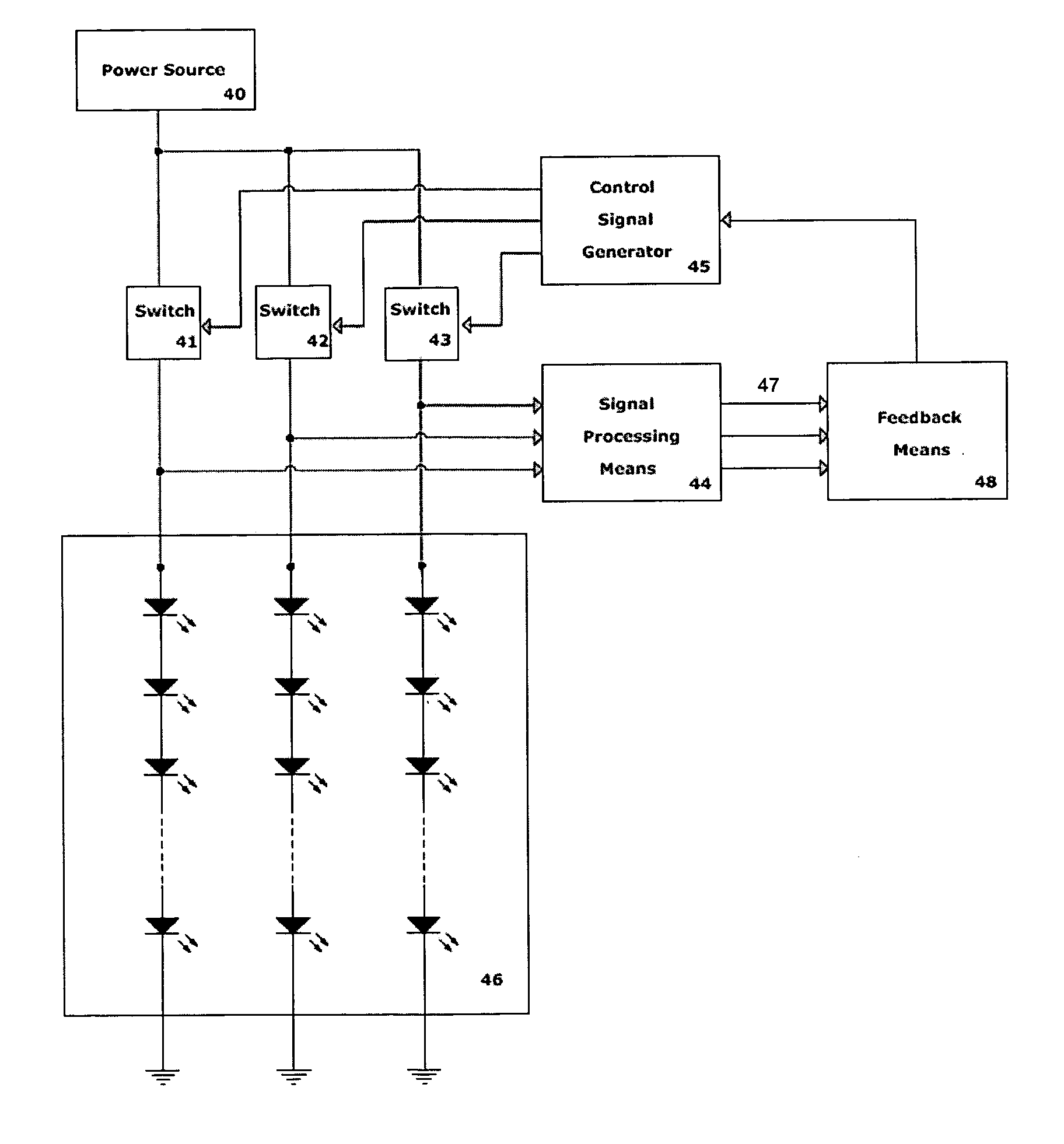
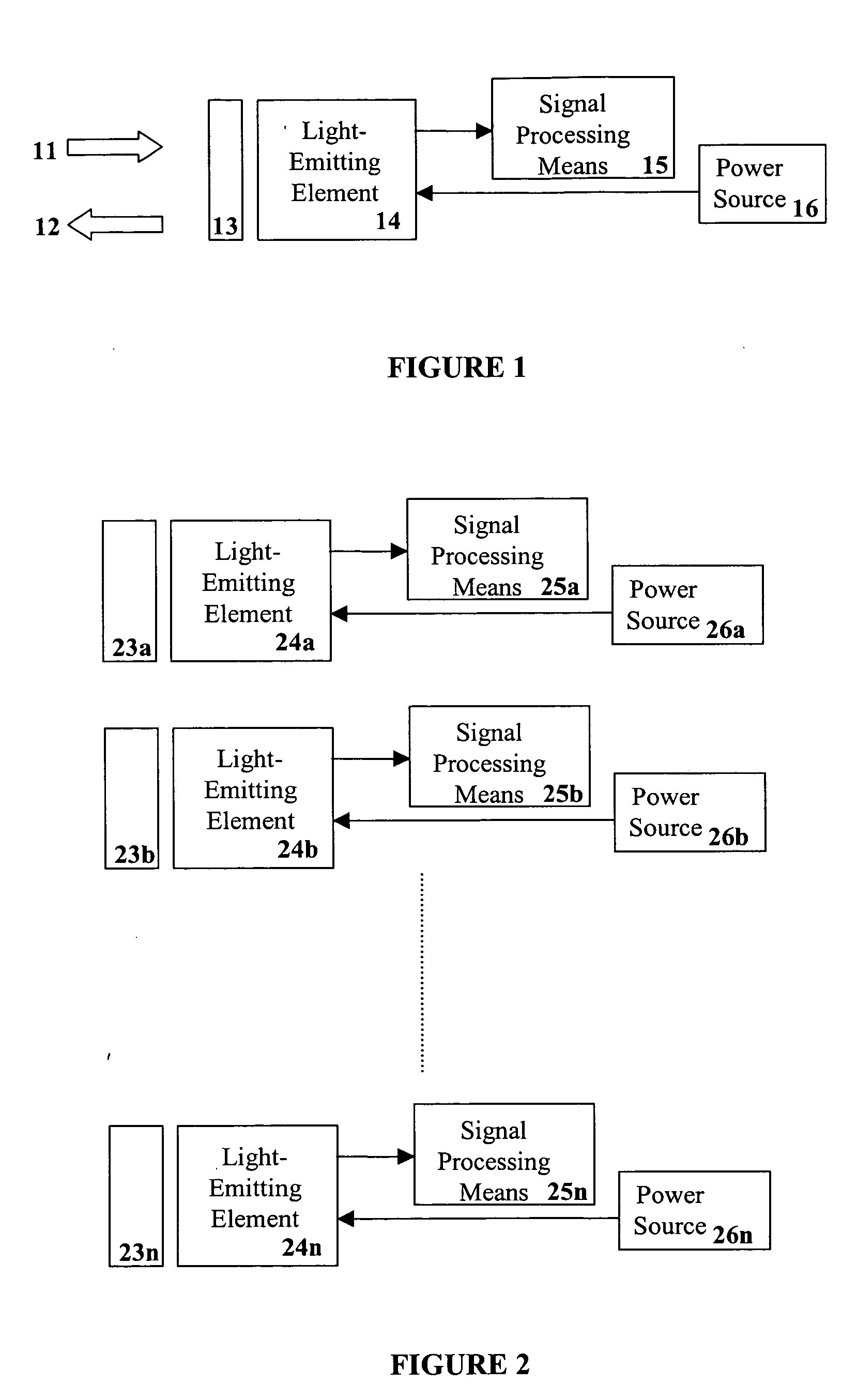
[0035] In one embodiment of the present invention as illustrated in FIG. 1, a single light-emitting element 14 receives switched (ON / OFF) power from power source 16. When in the ON state, the light-emitting element is activated and emits light 12. When in the OFF state, the light-emitting element 14 serves as a photodetector and measures the incident radiant flux 11 due to ambient light, for example. An optional filter 13, for example, a band pass filter that is substantially transparent to the spectral distribution of the emitted light may be employed to modify the spectral responsivity of the light-emitting element when operated as a photodetector. The detected signal is then provided to a signal processing means 15 for example, an amplifier circuit and / or an AID converter. In another embodiment a plurality of light-emitting elements may be used to detect ambient light.

[0036] In another embodiment of the present invention as illustrated in FIG. 2, a plurality of light-emitting el...


PUM


Abstract

The present invention provides a system and method for generating light using light-emitting elements and detecting the intensity and spectral power distribution of light using the same light-emitting elements as spectrally sensitive photodetectors. The light-emitting elements function in two modes, an ON mode and an OFF mode, wherein in the ON mode the light-emitting elements are activated and emit light of a particular frequency or range of frequencies. When in the OFF mode, the light-emitting elements are deactivated, wherein they do not emit light but serve to detect photons incident upon them thus generating an electrical signal representative of the intensity and spectral power distribution of the incident photons. The detected signal from the deactivated light-emitting elements can be used to provide photonic feedback to a lighting system, and thereby may be used to control the brightness and colour balance of the lighting system. In addition, the light-emitting elements may be arranged such that no spectrally selective filters or optics are necessary to block or focus light onto the light-emitting elements when in the detection or OFF mode.

Description

CROSS-REFERENCE TO RELATED APPLICATIONS [0001] This application claims the benefit of U.S. Provisional Patent Application No. 60 / 599,048, filed Aug. 6, 2004, which is hereby incorporated herein by reference.FIELD OF THE INVENTION [0002] The present invention pertains to the field of lighting systems and in particular to a lighting system including light-emitting elements for use as photonic emitters and detectors. BACKGROUND [0003] Recent advances in the development of semiconductor and organic light-emitting diodes (LEDs and OLEDs) have made these devices suitable for use in general illumination applications, including architectural, entertainment, and roadway lighting, for example. As such, these devices are becoming increasingly competitive with light sources for example, incandescent, fluorescent, and high-intensity discharge lamps. [0004] Optical feedback for a lighting system can be accomplished using a dedicated optical sensor, for example, a photodiode, phototransistor, or o...

Claims


Application Information

Patent Timeline
Patent Type & Authority Applications(United States)
IPC IPC(8): H05B39/00H05B44/00
CPCH05B33/0815H05B33/0869H05B33/0818H05B45/22H05B45/37
Inventor JUNGWIRTH, PAUL
Owner SIGNIFY HLDG BV
Why Eureka
Try Eureka